Rapid exchange infusion catheter

a catheter and rapid technology, applied in the field of catheters, can solve the problems of reducing the time required for medical procedures, and achieve the effects of high maneuverability, improved combination of low-profile, and large lumen siz

Inactive Publication Date: 2011-09-20
ABBOTT CARDIOVASCULAR
View PDF22 Cites 0 Cited by
  • Summary
  • Abstract
  • Description
  • Claims
  • Application Information

AI Technical Summary

Benefits of technology

[0006]The invention is directed to an infusion catheter with an elongated shaft having a guidewire lumen which has a proximal section and a common distal section extending to a distal port at a distal end of the shaft, and an infusion lumen which is in fluid communication with the distal port of the guidewire lumen and which joins the common distal section of the guidewire lumen at a location distal to the guidewire proximal port. The catheter is configured to prevent or inhibit a guidewire from slidably extending between the infusion and guidewire lumens. The configuration provides a highly maneuverable shaft with an improved combination of low-profile, flexibility, and a relatively large lumen size for rapid infusion.
[0008]Preferably, the passage from the infusion lumen to the common distal section of the guidewire lumen has a shape which provides a relatively large volume for infusion of the agent while at the same time restricting (e.g., preventing) passage of a guidewire therethrough. In a presently preferred embodiment, the restricted passage has a crescent-shape. The catheter is slidably disposed on a guidewire, typically by being back-loaded over the guidewire either before or after the guidewire is positioned in the patient's body lumen. Thus, the guidewire proximal end is threaded into the guidewire distal port, through the guidewire lumen, and out guidewire proximal port, and the catheter shaft design facilitates the ability to back-load the catheter onto the guidewire with the guidewire proximal end prevented or inhibited from entering the infusion lumen by the restricted, e.g., crescent-shaped, passage. The restricted passage can have a variety of suitable shapes, but by having a transverse dimension in at least one direction that is smaller than the guidewire (and thus smaller than the guidewire lumen as well), the restricted passage will prevent the guidewire from sliding into the infusion lumen.
[0009]The distal section of the guidewire lumen is commonly shared, in that it is used to accommodate a guidewire and to infuse an agent. As a result the catheter shaft maintains a flexible, low profile with a round tip configuration, unlike infusion catheters having two separate lumens extending side-by-side to the distal tip of the catheter for the guidewire and for infusion. Moreover, a catheter shaft of the invention is configured to provide relatively large sized lumens, including the infusion lumen to facilitate a fast rate of infusion. In contrast, attempts to minimize the profile increase caused by the addition of a separate infusion lumen by minimizing the size of the infusion lumen along the distal end of the catheter can disadvantageously increase the time required to perform the medical procedure.

Problems solved by technology

In contrast, attempts to minimize the profile increase caused by the addition of a separate infusion lumen by minimizing the size of the infusion lumen along the distal end of the catheter can disadvantageously increase the time required to perform the medical procedure.

Method used


Image

  • Rapid exchange infusion catheter
  • Rapid exchange infusion catheter
  • Rapid exchange infusion catheter

Examples


Embodiment Construction

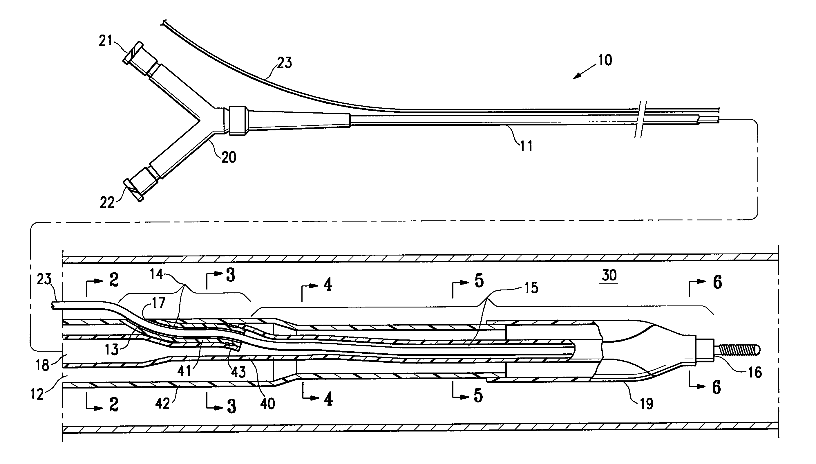
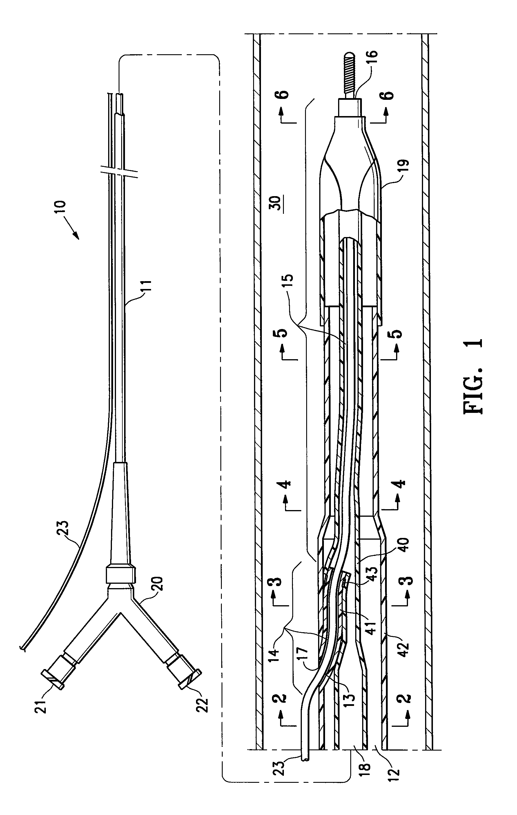
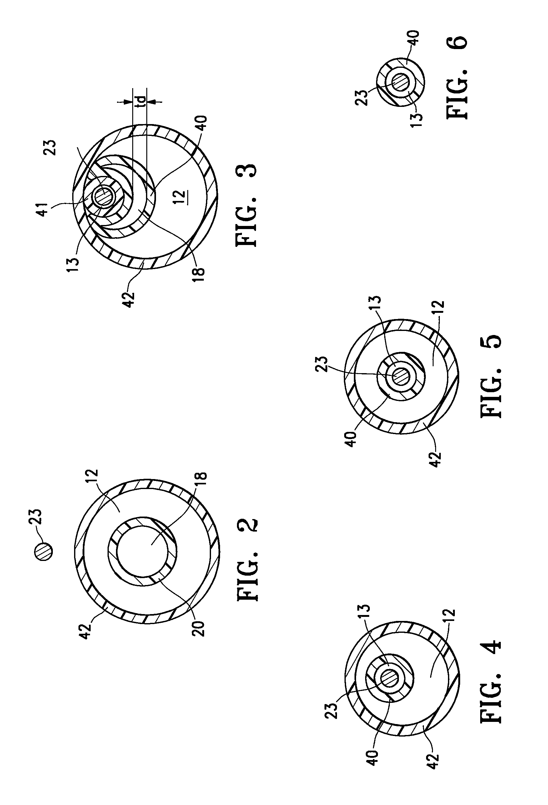
[0015]FIG. 1 illustrates an elevational, partially in section, view of an infusion balloon catheter 10 embodying features of the invention, generally comprising an elongated shaft 11 having a proximal end, a distal end, an inflation lumen 12, a guidewire lumen 13 which has a proximal section 14, a common distal section 15, and a distal port 16, and an infusion lumen 18 which is in fluid communication with the guidewire lumen distal port 16. An inflatable balloon 19 is on a distal section of the shaft, and has an interior in fluid communication with the inflation lumen 12. The catheter is a rapid exchange type catheter in that the guidewire lumen 13 extends from the distal port 16 at the shaft distal end to a guidewire proximal port 17 spaced distally from the proximal end of the shaft. A proximal adapter 20 on the proximal end of the catheter shaft 11 has a first arm with a port 21 which is in fluid communication with the inflation lumen 12 and which is configured to connect to an i...


PUM


Abstract

An infusion catheter and method, with an elongated shaft having a guidewire lumen which has a proximal section and a common distal section extending to a distal port at a distal end of the shaft, and an infusion lumen which is in fluid communication with the distal port of the guidewire lumen and which joins the common distal section of the guidewire lumen at a location distal to the guidewire proximal port. A restricted passage from the infusion lumen to the common distal section of the guidewire lumen has a smaller transverse dimension than the guidewire lumen and a guidewire slidably disposed in the guidewire lumen.

Description

CROSS-REFERENCES TO RELATED APPLICATIONS[0001]NoneBACKGROUND OF THE INVENTION[0002]The present invention relates generally to medical devices, and more particularly to a catheter for delivery of an agent to the coronary or peripheral vasculature.[0003]In the treatment of diseased vasculature, therapeutic agents have commonly been administered, typically as part of other interventional therapies such as angioplasty or stent delivery. Local, as opposed to systemic delivery is a preferred method of treatment in that smaller total levels of medication are administered in comparison to systemic dosages, yet are concentrated at a specific site. As a result, local delivery produces fewer side effects and achieves more effective results.[0004]A variety of methods and devices have been proposed for percutaneous drug delivery to a diseased region of the vasculature. For example, the catheter shaft can have a drug delivery lumen which extends to a port in the distal end of the catheter, and wh...

Claims


Application Information

Patent Timeline
Patent Type & Authority Patents(United States)
IPC IPC(8): A61M29/00A61F2/958
CPCA61M25/10A61M2025/0183
Inventor LEE, JEONG S.
Owner ABBOTT CARDIOVASCULAR
Why Eureka
Try Eureka