Intraocular lens insertion tool

a technology for insertion tools and intraocular lenses, which is applied in the field of intraocular lens insertion tools, can solve the problems of increased insertion resistance of intraocular lenses, increased risk of deformation or damage, and increased risk of bending or deformation of intraocular lenses, etc., and achieves excellent control, easy insertion in the tool body, and steady initial deformation

Inactive Publication Date: 2011-09-20
KOWA CO LTD
View PDF13 Cites 15 Cited by
  • Summary
  • Abstract
  • Description
  • Claims
  • Application Information

AI Technical Summary

Benefits of technology

[0011]With the foregoing in view, it is an object of the present invention to provide an intraocular lens insertion tool of novel construction adapted to minimize deformation of the intraocular lens, while effectively preventing the intraocular lens from rotating inside the insertion tube.Means for Solving the Problem
[0013]Specifically, the present invention resides in an intraocular lens insertion tool including a tool body having generally tubular shape for accommodating an intraocular lens, and a plunging member inserted into the tool body from a rear in an axial direction and moved forward for inserting into an eye the intraocular lens such that the intraocular lens undergoes compact deformation in association with forward displacement in the axial direction by the plunging member and is pushed out, characterized in that: an insertion tube disposed at a distal end section of the tool body and adapted for insertion into the eye, viewed perpendicular to a direction of extension thereof, has across an entire length from a proximal end opening to a distal end opening of the insertion tube a cross section wherein an upper and lower portions have traverse linear portions that extend substantially parallel in a width direction, and left and right portions that connect smoothly with the upper and lower portions; that in at least one part of the insertion tube in the direction of extension towards the proximal end opening, the left and right portions have longitudinal linear portions that extend substantially parallel in a vertical direction; and that the upper and lower portions gradually approach one another due to a radius of curvature that decreases gradually in an inwardly concave curved shape towards the distal end opening to form a tapered portion having a reduced cross-sectional area, thus producing the distal end opening of substantially oval shape.
[0015]According to the intraocular lens insertion tool of the present invention, the left and right planes inside the insertion tube connect to the upper and lower planes smoothly through common tangents with no inflection point. Thus, even if the intraocular lens should happen to experience displacement in the circumferential direction of the insertion tube, it will be possible to prevent localized excessive force from being exerted on the intraocular lens, and to prevent as much as possible deformation or damage to the intraocular lens.
[0017]Additionally, in a preferred mode of the intraocular lens insertion tool of the present invention, the cross section of the insertion tube viewed perpendicular to the direction of extension will become gradually smaller towards the tapered portion across the entire length from the proximal end opening to the distal end opening of the insertion to be, so that the tapered portion is formed across the entire length of the insertion tube. With this arrangement, the length dimension of the insertion tube can be used effectively to bring about deformation of the intraocular lens to smaller size.
[0018]In another preferred mode of the intraocular lens insertion tool of the present invention, wherein as viewed in cross section in a direction of extension, the lower portion of the tapered portion has a linear shape, whereas the upper portion has an inwardly convex, arcuate curved portion of substantially unchanging curvature which gradually approaches the lower portion towards the distal end opening. With this arrangement, the intraocular lens can be deformed more smoothly while being clamped stably against the lower plane.
[0020]With this arrangement, the intraocular lens can be rested easily in the tool body. Then, by compressing the intraocular lens resting on the stage from above with the clamping projection, the intraocular lens can be steadily deformed to upwardly concave shape while being clamped against the lower plane of the recessed groove. Thus, steady initial deformation of the intraocular lens when pushed into the insertion tube can be achieved with excellent control, making it possible for deformation of the intraocular lens inside the insertion tube to take place more steadily and smoothly.

Problems solved by technology

However, an insertion tool constructed in this manner poses a risk that due to becoming lodged in this way, the intraocular lens may experience unnecessary bending or be subjected to localized action of excessive levels of deformation or stress.
For this reason, the insertion resistance of the intraocular lens will be greater, with an attendant risk or deformation or damage when forcibly pushed.
An additional difficulty is the problem, in terms of the mold etc., of forming an inflection point having a sufficiently acute angle to hold up the intraocular lens and prevent it from rotating.

Method used


Image

  • Intraocular lens insertion tool
  • Intraocular lens insertion tool
  • Intraocular lens insertion tool

Examples


Embodiment Construction

[0035]In order to provide a more specific understanding of the present invention, preferred embodiments of the invention will be discussed in detail below with reference to the accompanying drawings.

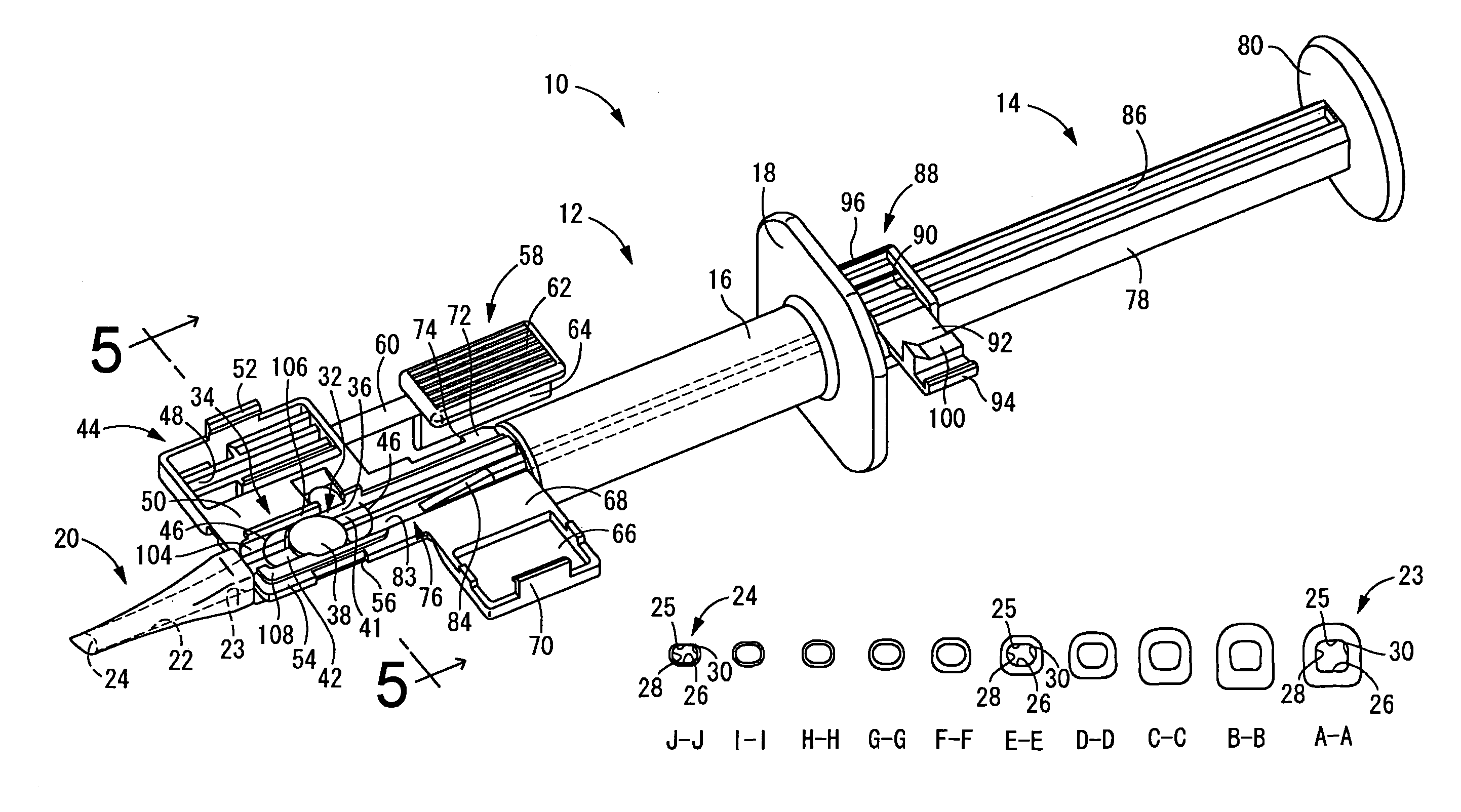
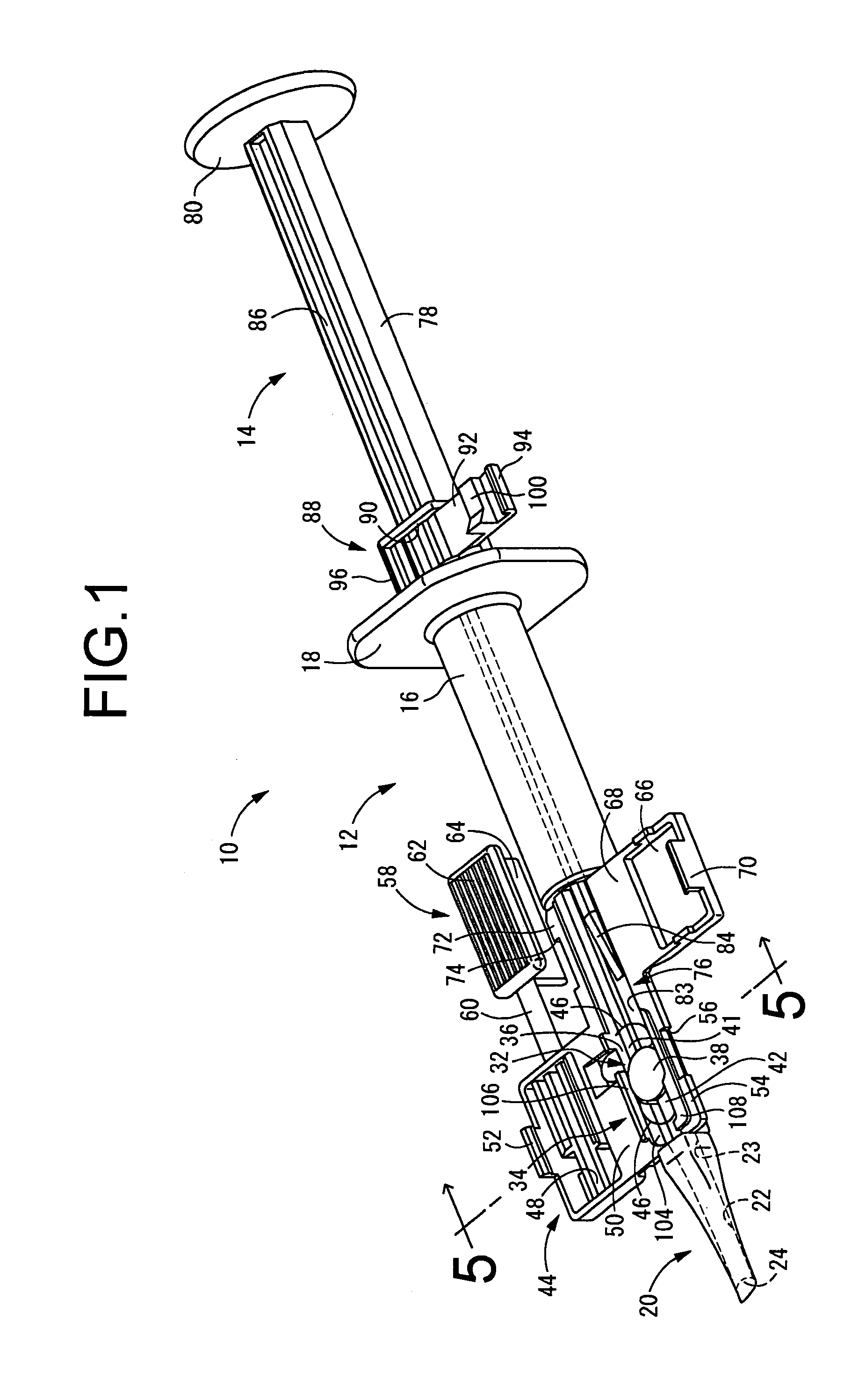
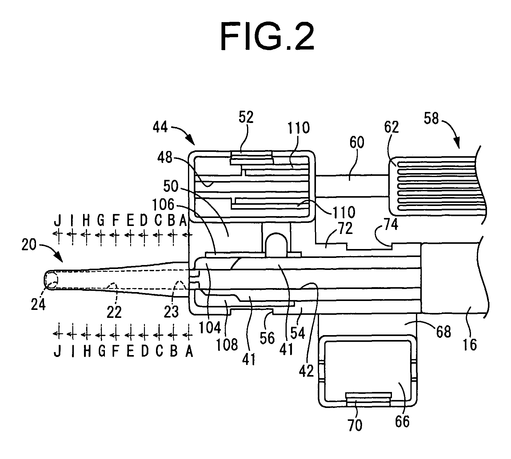
[0036]First, an intraocular lens insertion tool 10 according to a first embodiment of the present invention is depicted in FIG. 1. The insertion tool 10 includes a tool body 12 having generally tubular shape perforated in its interior throughout its entire length and open at the front and back ends, into which inserts a plunger 14. Herein, ‘front’ refers to the direction of extension of the insertion tool 10 (leftward in FIG. 1), and ‘upward’ refers to the upward direction in FIG. 1. ‘Left-right direction’ refers to the left-right direction of the insertion tool 10 in rear view (in FIG. 1, the lower right side is left and the upper left side is right).

[0037]The tool body 12 has a main tubular section 16 of generally round tubular shape, and at the back end of the main tubular section 16 ...


PUM


Abstract

An insertion tool of an intraocular lens permits the lens to be deformed while rotation of the lens in an insertion tube is effectively prevented. Upper and lower flat planes are formed to spread flatly over a length of a through hole in the insertion tube and the upper and lower flat planes are connected smoothly with right and left wall faces over the length of the through hole. The right and left wall faces have longitudinal linear portions extending substantially in parallel in a vertical direction on a proximal end opening side. With its radius of curvature decreasing gradually in a covered shape which becomes inwardly concave as it approaches a distal end opening the upper flat plane gradually approaches the lower flat plane, and a tapered portion having a reduced cross-sectional area is formed, thus obtaining the distal end opening of substantially oval shape.

Description

TECHNICAL FIELD[0001]The present invention relates to an intraocular lens insertion tool used to insert an intraocular lens into the eye.BACKGROUND ART[0002]One method employed in the past in the field of cataract surgery involves extracting the intracapsular crystalline lens through a surgical incision made in ocular tissue such as the cornea (sclera) or anterior capsule section of the crystalline lens, and once the crystalline lens has been removed, inserting an intraocular lens serving as a replacement for the crystalline lens back through the incision and positioning it within the capsule.[0003]Particularly in recent years, methods that employ an intraocular lens insertion tool like that disclosed in Patent Document 1 and Patent Document 2 have come into widespread use. Typically, the intraocular lens will be inserted into the eye by first inserting the distal orifice of an insertion tube provided at the distal end section of the body of the tool through a surgical incision, the...

Claims


Application Information

Patent Timeline
Patent Type & Authority Patents(United States)
IPC IPC(8): A61F2/16
CPCA61F2/1678A61F2/16A61F9/007
Inventor TANAKA, MASAYOSHI
Owner KOWA CO LTD
Why Eureka
Try Eureka