Filter element and method

a filter element and filter element technology, applied in the field of filter elements, can solve the problems of significant gas flow contamination, prior art filtering for e.g. diesel engines cannot solve, and no filter element suitable for use, etc., and achieve the effects of low solidity, high loft, and high porosity

Inactive Publication Date: 2011-09-20
DONALDSON CO INC
View PDF441 Cites 87 Cited by
  • Summary
  • Abstract
  • Description
  • Claims
  • Application Information

AI Technical Summary

Benefits of technology

[0017]We have found a filter medium and filter element and a unique filter structure capable of efficiently removing heavy loadings of more than one type of particulate from a mobile fluid stream under a variety of harsh conditions. The medium of the invention combines high strength and excellent filtration properties with ease of manufacturing both the media and filter elements made from the media. The invention comprises a plurality of nonwoven, thermally bonded filter media, stacked in a housing to form a filter element. Filter media of the invention are made by incorporating substantial proportions of an organic or inorganic media fiber, a bicomponent thermoplastic binder fiber, optionally a resin binder, optionally a secondary fiber such as a thermoplastic fiber, and optionally other filtration materials.

Problems solved by technology

We have not found any filter elements that are suitable for use in heavy-duty engine filtration applications where very high levels of both solid and oily aerosol particulate are encountered.
The prior art filters for e.g. diesel engines does not solve the problems presented by newer generation engines where the level of soot passed through the filter is much higher than engines of past generations.
Engines operating in such systems as trucks, farm machinery, boats, buses, and other systems generally comprising diesel engines, may have significant gas flows contaminated as described above.
New environmental restrictions in many countries now severely limit these emissions.
However, recently diesel engines have been manufactured that generate excessive amounts of soot.
The life of the filter element is thereby severely reduced due to clogging of the first few layers of the filter media.
Aerosols in particular are challenging in filtration applications.
The ability to achieve certain filtration attributes such as pore size, basis weight, thickness, permeability and efficiency are limited by the manufacturing techniques used to make the paper layers and by the components useful in such layers.
Because aerosols may be as small as 1 nm diameter or as large as 1 mm (W. Hinds, Aerosol Technology: Properties, Behavior, and Measurement of Airborne Particles 8, 2nd ed., © 1999 J. Wiley & Sons), conventional technologies are not suitably flexible to effectively accommodate the range of particle sizes in which aerosols may be encountered in fluid streams.
However, none of these media are suitable for use in diesel engines where very high soot and oily aerosol loading is encountered in CCV filtration applications.

Method used


Image

  • Filter element and method
  • Filter element and method
  • Filter element and method

Examples


example 1

[0124]Wet-laid filter media were prepared according to the following technique. Glass and synthetic fibers were dispersed separately in 1 L water where the pH was first adjusted to about 3 using sulfuric acid. The fibers were slurried by blending in a Waring 2 speed blender (model # 7009G, available from Waring Products of Torrington, Conn.). The fiber slurries were then diluted to a total of 5 L with 4 L of water and blended for an additional 2 minutes or more. The mixed slurry was transferred to a standard a Formax 12×12 inch G-100 handsheet mold (available from Bescorp Inc. of Dover, N.H.), in which a carrier sheet of Reemay 2200 (available from Fiberweb plc of Old Hickory, Tenn.) was positioned. The sheet was carefully flooded so as to ascertain that no air bubbles were entrained. The water was then drained from the slurry. The wet sheet was dried and bonded using an Emerson Speed Dryer, Model 135 (available from Kalamazoo Paper Chemicals of Richland, Mich.) flat sheet dryer at ...

example 2

[0127]Air laid filter media of the present invention were obtained from Tangerding Bocholt GmbH of Bocholt, Germany. Tangerding reference number TB 180-T05 is referred to as FM-3 (Filter Media 3) in this and the following Examples. Tangerding reference number FF 320-T05-2 is referred to as FM-4 in this and the following Examples. And Tangerding reference number FF 180-T05-4 NP-0256 / 2 is referred to as FM-5 in this and following Examples. Composition of air-laid filter media, FM-3, FM-4, and FM-5 are shown in Table 2. Also shown in Table 2 are basis weight, thickness at two different pressures and the fraction of the thickness compressed between the two pressures, calculated XY pore size, and permeability for air laid filter media FM-3, FM-4, and FM-5.

[0128]

TABLE 2Composition and properties of experimental air-laid filter media.PropertyUnitsFM-3FM-4FM-5Composition(none)24 um polyester16.7 um polyester16.7 um polyesterbicomponent +bicomponent +bicomponent +polyesterpolyesterpolyesterB...

example 3

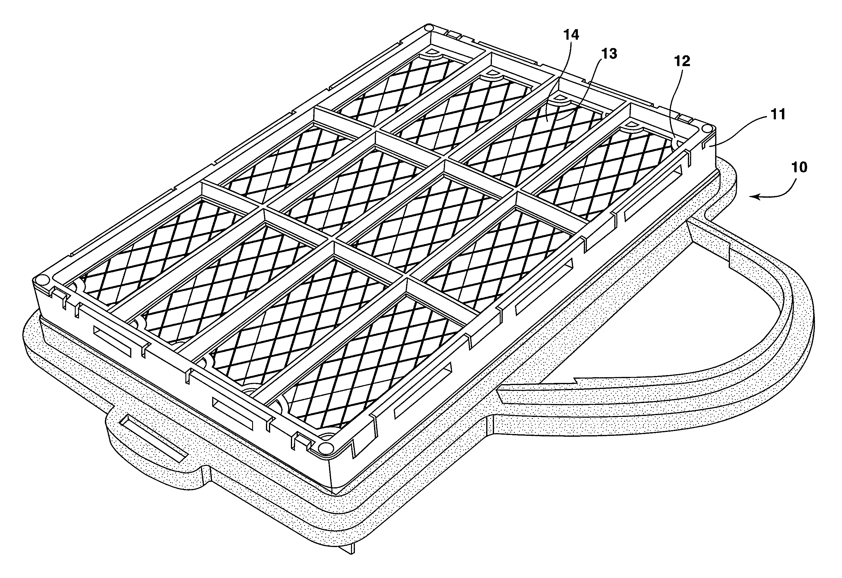
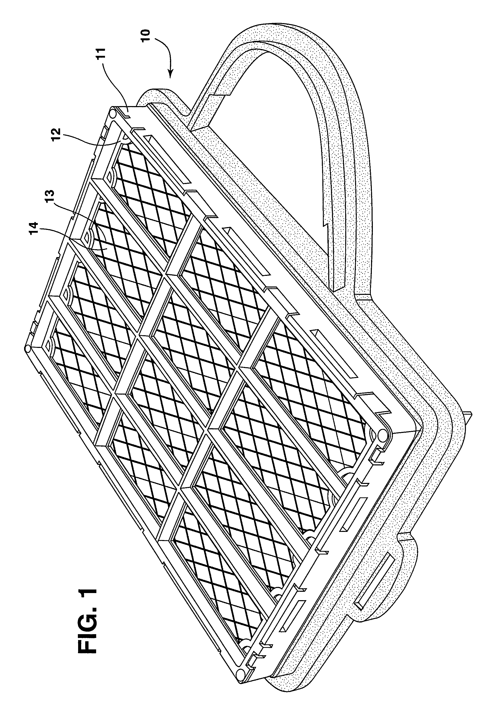
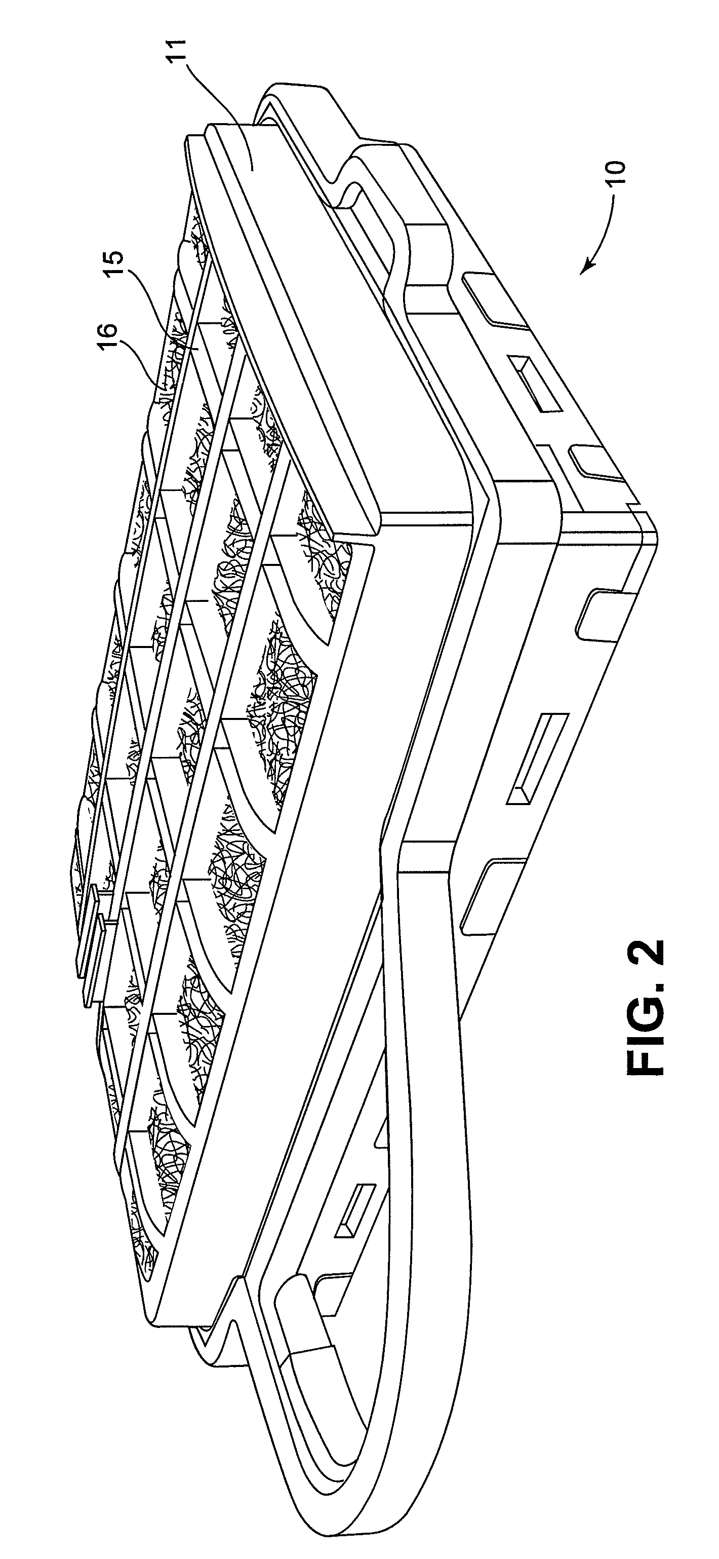
[0129]Filter media from the examples above were cut into rectangular sheets 21.6 cm×14.5 cm. The sheets were layered to form a filter element. The filter elements were enclosed in a housing having a perforate support on both sides, as can be seen in FIGS. 1-4. A housing, support, and filter element together form a filter structure. The filter structures were constructed using multiple layers of filter media as shown in Table 3. The media was backed on the downstream side with an expanded metal mesh in a diamond pattern, as is seen in FIG. 1. The media was compressed to 3.4 cm between the perforate supports at the upstream and downstream ends of the filter structure.

[0130]A control filter structure, FStr-CTRL, was obtained for comparison in testing to FStr-1, -2, and -3 in Example 4, below. FStr-CTRL is a filter marketed for use in diesel engines and is available as Part No. SO40029 from the Donaldson Company, Inc. of Minneapolis, Minn.

[0131]

TABLE 3Filter structures formed from layer...


PUM

PropertyMeasurementUnit
pore sizeaaaaaaaaaa
diameteraaaaaaaaaa
pore sizeaaaaaaaaaa

Abstract

A filter element having multiple formed layers of filtration media is disclosed. The media are layered so as to form a pore size gradient. The filter element is capable of removing both solid and liquid particulates from a moving fluid stream. The filter element has high strength and compressibility. The layers can be supported on a porous or perforate support to provide mechanical stability during filtering operations. The filtration media layers can be formed into various filter element forms such as panels, cartridges, inserts, and the like.

Description

CROSS REFERENCE TO RELATED APPLICATION[0001]This application claims priority from provisional application Ser. No. 60 / 891,061, filed Feb. 22, 2007, and which is incorporated herein by reference.FIELD OF THE INVENTION[0002]The invention relates to a filter element formed by multiple layers of non-woven filter media of that is suitable for simultaneous solid and liquid particulate removal by virtue of high permeability, efficiency, loading capability, and other filtration parameters. The multiple layers of filter media are stacked so as to form a pore size gradient. The filter element is capable of removing both solid and liquid particulates from a moving fluid stream. The filter element has high strength and compressibility.[0003]The invention relates to non-woven media layers that can survive challenging operating conditions, such as variation in flow rate, temperature, pressure and particulate loading while removing substantial particulate and aerosol loads from the fluid stream. T...

Claims


Application Information

Patent Timeline
Patent Type & Authority Patents(United States)
IPC IPC(8): B01D59/50
CPCB01D39/163B01D39/2024B01D46/003B01D46/10B01D46/546F02M35/024Y10S55/05B01D2239/0258B01D2239/064B01D2239/0681B01D2275/10B01D2239/0216
Inventor ADAMEK, DANIEL E.CAPPUYNS, JANMOREAU, EGIDE EMMANUEL PAUL BAUDRYOUYANG, MINGROGERS, ROBERT M.
Owner DONALDSON CO INC
Why Eureka
Try Eureka