Supercharge Your Innovation With Domain-Expert AI Agents!

Drive mechanisms for human-powered machines

a technology of drive mechanism and crankshaft, which is applied in the direction of mechanical equipment, sports apparatus, transportation and packaging, etc., can solve the problems of reducing the potential power that could be applied to the crankshaft, prone to slippage under high rearward or upward force, and not feeling natural

Inactive Publication Date: 2011-09-27
SMITH ROBERT M
View PDF17 Cites 22 Cited by
  • Summary
  • Abstract
  • Description
  • Claims
  • Application Information

AI Technical Summary

Benefits of technology

This solution improves pedaling efficiency and power transfer by alerting cyclists to dead points, allowing for better muscle development and increased speed, while maintaining conventional bicycle operation and usability.

Problems solved by technology

With this system, unless the foot or cycling shoe is very firmly fastened to the pedal by the strap, it is prone to slip out under high levels of rearward or upward force.
However by reducing the inertia, the cyclist avoids the physical effort needed to overcome dead points, therefore does not build up the relevant muscles, and thereby reduces the potential power that could be applied to the cranks.
Also, if the bicycle is travelling at a constant speed the cyclist's leg will be speeding up and slowing down dependent on which point of the revolution they are at, a situation which has been found to not feel natural.
It is a more natural action to pedal at a constant angular velocity, but this will cause the bicycle to be subject to surging and slowing during every crank revolution.
However, one of the problems regularly experienced has been with actual identification of the occurrence or onset of such a dead point.
Such has meant that, with conventional crank systems for bicycles, it has been difficult for the cyclist to actually detect the occurrence of a dead point, let alone try to compensate therefor, this especially when the legs have become fatigued or, in the alternative, when tiredness leads to a lapse in concentration and a variation in the pedalling technique.

Method used


Image

  • Drive mechanisms for human-powered machines
  • Drive mechanisms for human-powered machines
  • Drive mechanisms for human-powered machines

Examples


Embodiment Construction

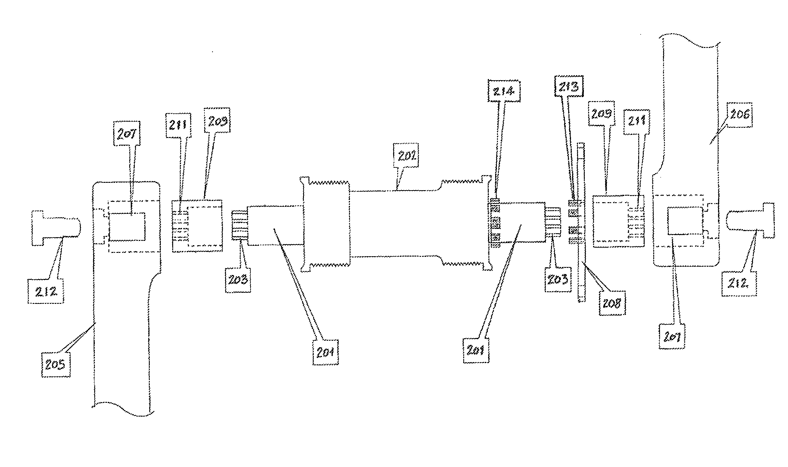
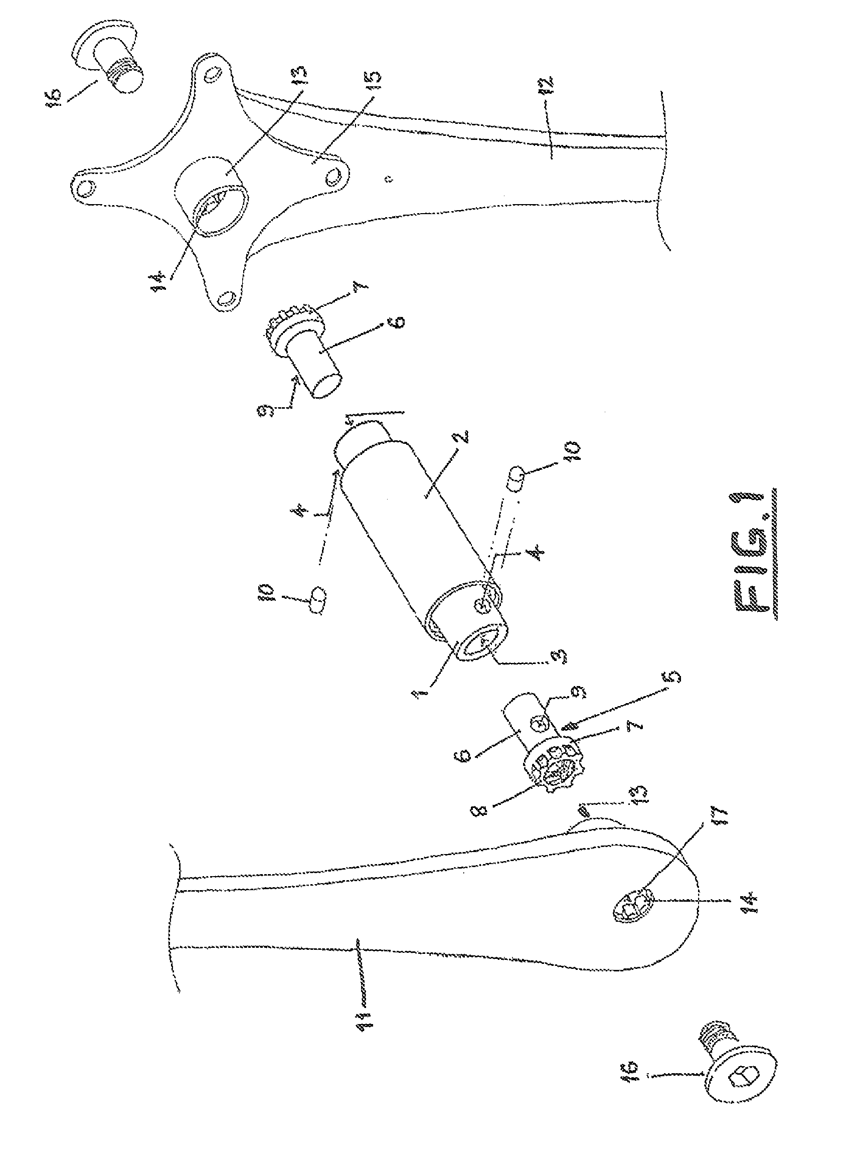
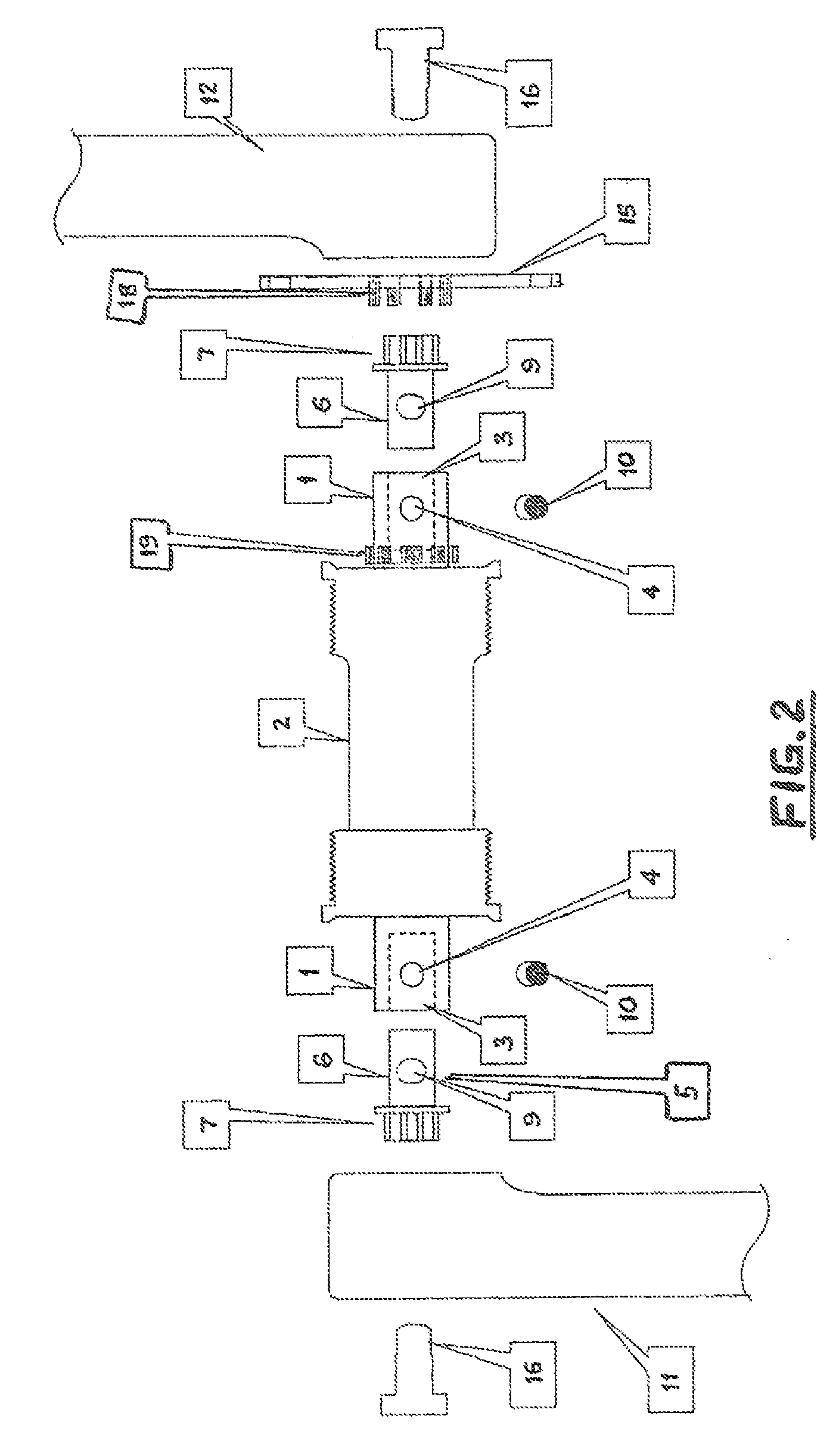
[0042]With reference firstly to the embodiment of FIG. 1, the arrangement shown therein includes a crankshaft or spindle 1 which is disposed longitudinally or axially within a crank spindle housing 2 and protrudes from each end thereof (as shown). In an especially preferred embodiment low friction bearings of any known type (not shown) may be employed to support the spindle 1 within the housing 2 and to allow for smooth relative rotation therebetween.

[0043]In this embodiment the crankshaft or spindle 1 is in the form of a substantially cylindrical member having bores or hollow sections 3 formed in each free end thereof. Displaced from each free end of the crank spindle 1, and at a predetermined location therealong and extending substantially radially thereinto, is an aperture or recess 4 which extends into the associated hollow section 3, for a purpose to be explained hereinafter.

[0044]In this embodiment there are provided respective left and right stub axles or drive transfer means...


PUM


Abstract

An improved power transfer mechanism for use on a human-powered machine, adapted to be drivingly connected to a power take-off device of said machines, includes: a housing adapted in use, to be disposed within a frame of said human-powered machine; at least one crankshaft adapted to be disposed within said housing; respective left-side and right-side crank arms each adapted to be drivingly associated with an end of said at least one crankshaft; and drive transfer means adapted to co-operate with said at least one crankshaft and each associated crank arm, the arrangement being such that a first member of the group comprising and left-side and right-side crank arms and said power take-off device is adapted to be attached to said at least one crankshaft, such that each of the second and third of said members is adapted to be rotatable relative to said first of said members, and each other, only to a limited and controlled degree, whilst not be movable axially or in a longitudinal direction relative to said at least one crankshaft.

Description

FIELD OF THE INVENTION[0001]The present invention relates, in general terms, to an improved power transfer means or drive mechanism for a human-powered machine, as for example a bicycle. More particularly, but not exclusively, the invention relates to an improved drive mechanism which, if correctly utilised by the rider / user, will allow for an improved pedalling technique and / or the maintenance of an optimum pedalling technique, with a resultant improvement in function or operation of the human-powered machine itself.[0002]These days cycles, whether bicycles of the mobile type or cycles of the stationary / exercise type, are enjoying usage on an ever-increasing scale, for both sporting and recreational pastimes or for general health purposes. Throughout the ensuing description reference will be made to a particular and preferred embodiment or context of usage of the present invention, namely in a bicycle of the on-road or mobile type. It should be understood, however, that the present...

Claims


Application Information

Patent Timeline
Patent Type & Authority Patents(United States)
IPC IPC(8): B62M1/02B62M1/36
CPCB62M3/003B62M3/00A63B22/0605A63B69/16A63B2220/54Y10T74/2164Y10T74/2167
Inventor SMITH, ROBERT M.
Owner SMITH ROBERT M
Features
  • R&D
  • Intellectual Property
  • Life Sciences
  • Materials
  • Tech Scout
  • Unparalleled Data Quality
  • Higher Quality Content
  • 60% Fewer Hallucinations
Learn More