Microscopy imaging system and method employing stimulated raman spectroscopy as a contrast mechanism

a technology of raman spectroscopy and microscope imaging, which is applied in the field of vibrational microscopy and imaging systems, can solve the problems of poor spatial resolution, limited spatial resolution, and general direct involvement of infrared microscopy

Active Publication Date: 2011-09-27
PRESIDENT & FELLOWS OF HARVARD COLLEGE
View PDF10 Cites 13 Cited by
  • Summary
  • Abstract
  • Description
  • Claims
  • Application Information

AI Technical Summary

Problems solved by technology

Infrared microscopy, which generally involves directly measuring the absorption of vibrational excited states in a sample, is limited by poor spatial resolution due to the long wavelength of infrared light, as well as by a low penetration depth due to a strong infrared light absorption by the water in biological samples.
Raman microscopy has improved optical resolution and penetration depth as compared to infrared microscopy, but the sensitivity of Raman microscopy is rather poor be...

Method used


Image

  • Microscopy imaging system and method employing stimulated raman spectroscopy as a contrast mechanism
  • Microscopy imaging system and method employing stimulated raman spectroscopy as a contrast mechanism
  • Microscopy imaging system and method employing stimulated raman spectroscopy as a contrast mechanism

Examples


Embodiment Construction

The following description may be further understood with reference to the accompanying drawings in which:

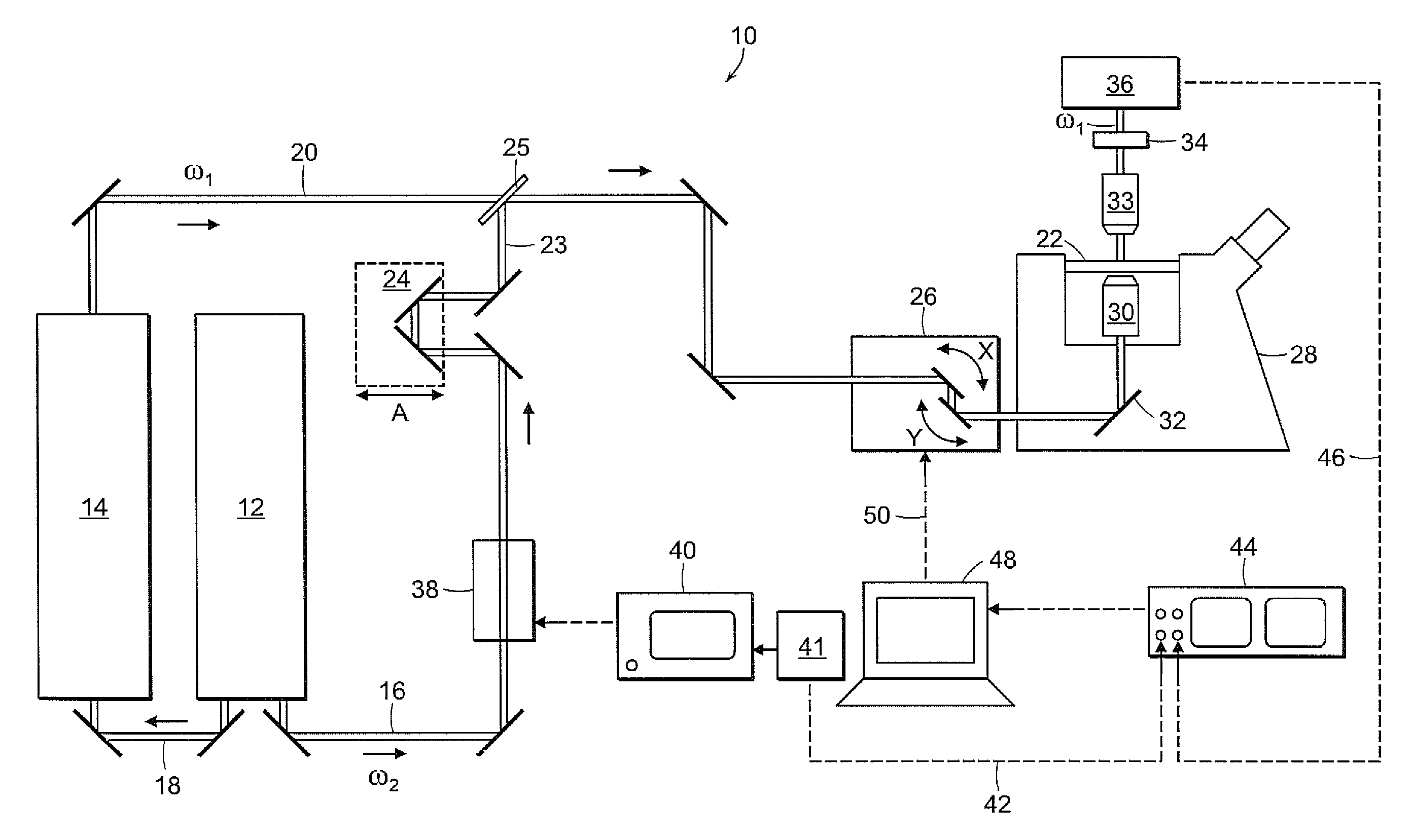
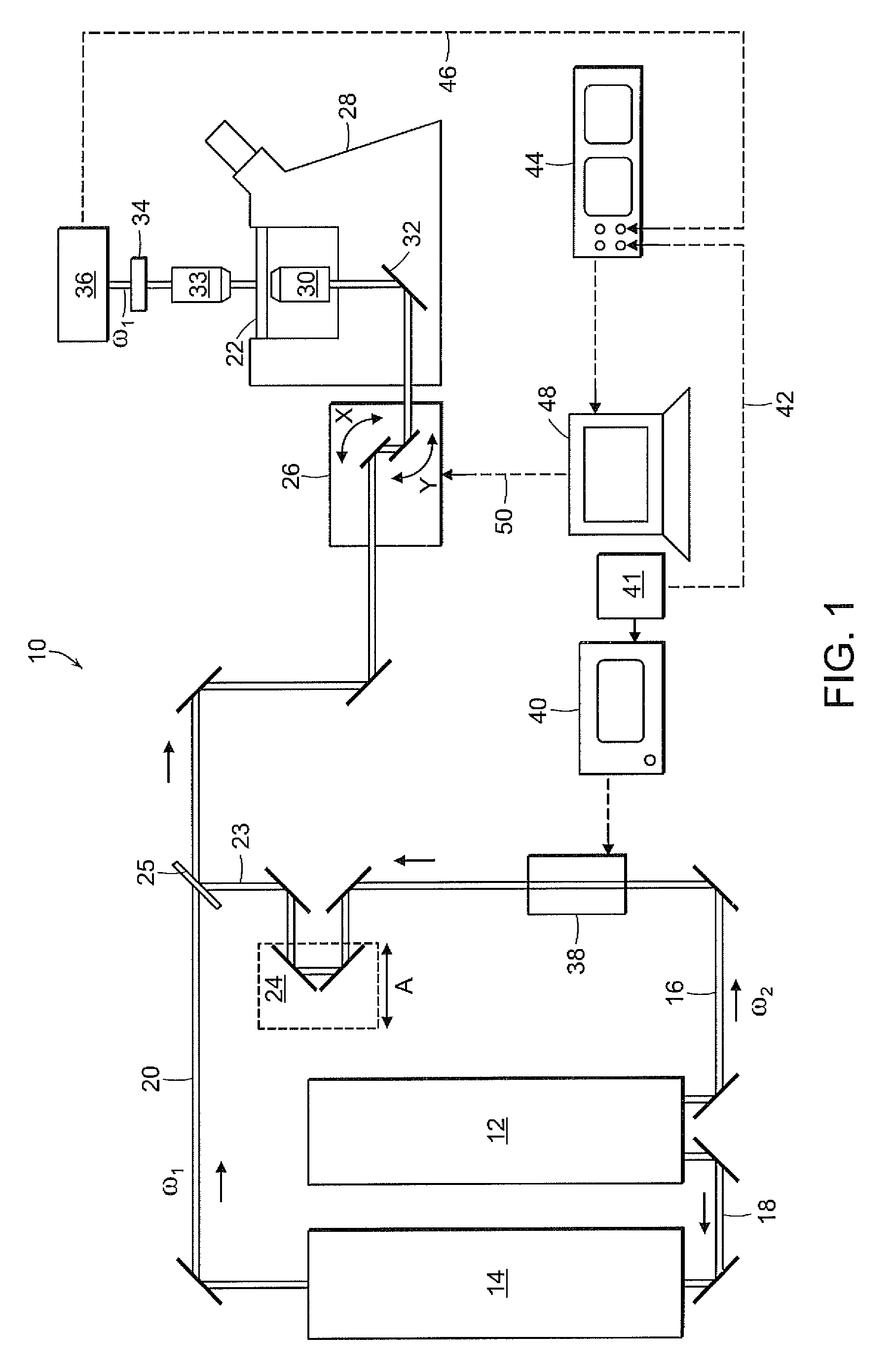
FIG. 1 shows an illustrative diagrammatic view of a microscopy imaging system in accordance with an embodiment of the invention;

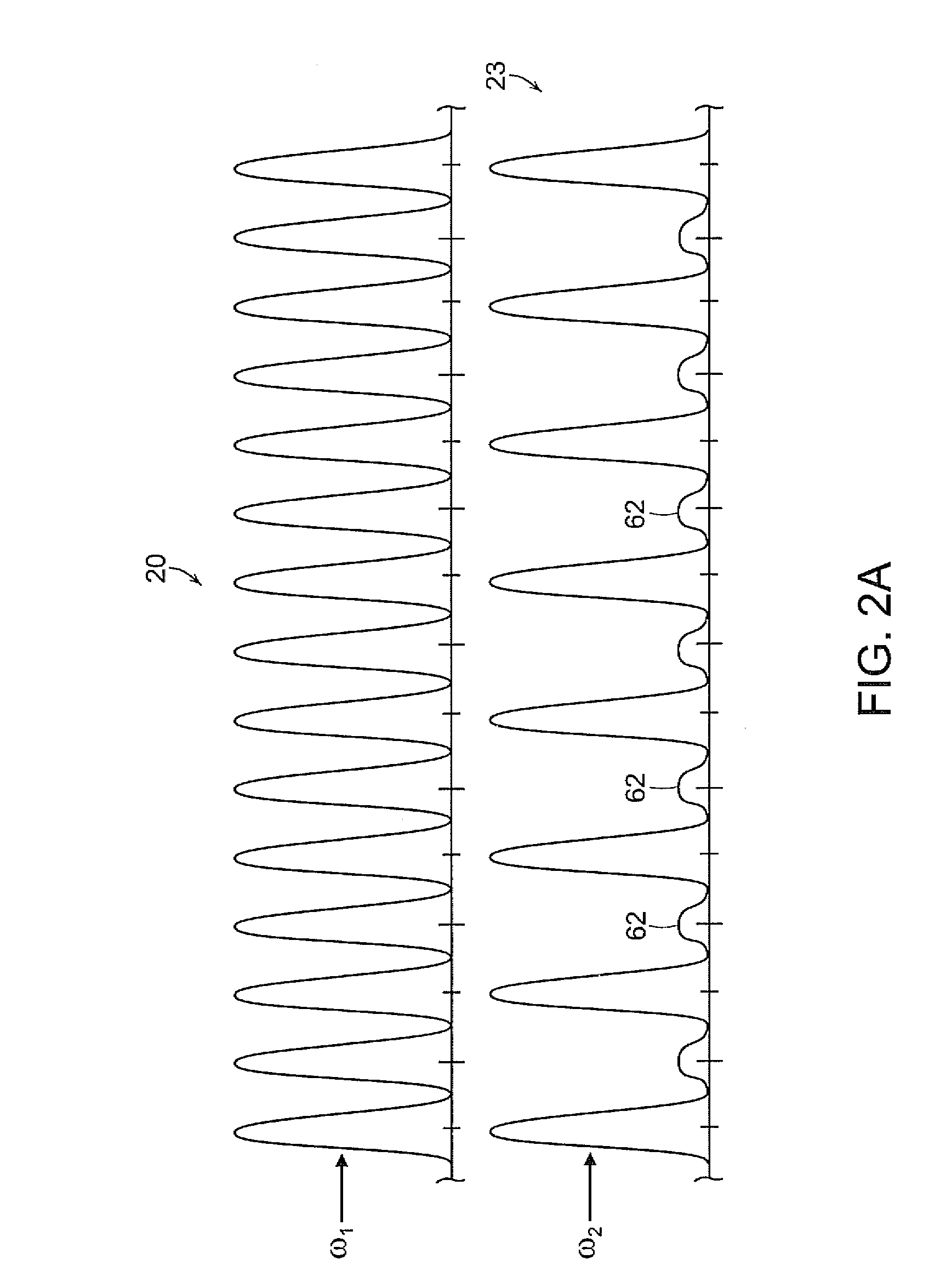
FIGS. 2A-2D show illustrative graphical representations of two pulse trains, one of which is modulated using amplitude modulation, polarization modulation, time-shifting modulation, and frequency modulation respectively in accordance with various embodiments of the invention;

FIG. 3 shows an illustrative graphical representation of Raman intensity as a function of a difference between frequencies of two pulse trains in a system in accordance with an embodiment of the invention;

FIGS. 4A and 4B show illustrative diagrammatic views of microscopy imaging systems in accordance with further embodiments of the invention that provide frequency modulation of a train of pulses;

FIG. 5 shows an illustrative graphical representation of the power spectrum of the laser,...


PUM


Abstract

A microscopy imaging system includes a first light source for providing a first train of pulses at a first center optical frequency ω1, a second light source for providing a second train of pulses at a second center optical frequency ω2, a modulator system, an optical detector, and a processor. The modulator system is for modulating a beam property of the second train of pulses at a modulation frequency f of at least 100 kHz. The optical detector is for detecting an integrated intensity of substantially all optical frequency components of the first train of pulses from the common focal volume by blocking the second train of pulses being modulated. The processor is for detecting, a modulation at the modulation frequency f, of the integrated intensity of the optical frequency components of the first train of pulses to provide a pixel of an image for the microscopy imaging system.

Description

BACKGROUNDThe invention generally relates to vibrational microscopy and imaging systems, and relates in particular to vibrational imaging systems employing Raman scattering.Conventional vibrational imaging techniques include, for example, infrared microscopy, Raman microscopy, and coherent anti-Stokes Raman scattering (CARS) microscopy.Infrared microscopy, which generally involves directly measuring the absorption of vibrational excited states in a sample, is limited by poor spatial resolution due to the long wavelength of infrared light, as well as by a low penetration depth due to a strong infrared light absorption by the water in biological samples.Raman microscopy records the spontaneous inelastic Raman scattering upon a single (ultraviolet, visible or near infrared) continuous wave (CW) laser excitation. Raman microscopy has improved optical resolution and penetration depth as compared to infrared microscopy, but the sensitivity of Raman microscopy is rather poor because of the...

Claims


Application Information

Patent Timeline
IPC IPC(8): G01J3/44
CPCG01J3/44G01N21/65G01N2021/653G01N2021/655G01N2021/656G01N2201/08
Inventor XIE, XIAOLIANG SUNNEYFREUDIGER, CHRISTIANMIN, WEI
Owner PRESIDENT & FELLOWS OF HARVARD COLLEGE
Why Eureka
Try Eureka