
Closable loop access guide catheter

a catheter and loop technology, applied in the field of interventional catheters, can solve the problems of catheter backing, difficult positioning of the guiding catheter into the ostium of the vessel to be treated, and exacerbate the problem of catheter backing

Inactive Publication Date: 2011-10-04
THIELEN JOSEPH MICHAEL +1
View PDF2 Cites 15 Cited by
  • Summary
  • Abstract
  • Description
  • Claims
  • Application Information

AI Technical Summary

Benefits of technology

"The present invention is an access guide catheter that can be used to deliver interventional catheters to the carotid arteries and other vessels in the body. The catheter can be placed through a sheath or guidewire and has a closed loop conformation that allows for good support and easy delivery of interventional catheters. The catheter can be used to treat blockages in the carotid arteries and has a flexible distal region that can be directed into a loop for better access. The catheter can be placed from either the left or right side of the body and can provide a closed loop for delivery of a catheter from one vessel and back in an opposing direction. The catheter can be tensioned to provide a larger radius of curvature bend than would be possible in the absence of a closed loop. The invention allows for early delivery of a temporary filter wire to protect the internal carotid artery from embolization of debris."

Problems solved by technology

Positioning of the guiding catheter into the ostium of the vessel to be treated can often be difficult, especially in diseased vasculature or in vessels that require the catheter to undergo a significant turn in the direction of travel.
An additional problem that often occurs when trying to advance the percutaneous catheters through the guide catheter is that the guide catheter does not provide enough support for delivery of the percutaneous catheter and can result in the guide catheter backing out from the ostium of the vessel leading to the lesion to be treated.
This problem can be exacerbated if the interventional catheter is stiff or carries a stiff element such as a stent thereby requiring a larger radius of curvature in the guide catheter to allow delivery of the interventional catheter or device.
In diseased aortas the access to these ostii can be difficult and the support provided by this access can be inadequate to allow advancement of the therapeutic catheter.
Interventional catheters that are stiff and cannot undergo a tight turn such as a stent delivery catheter system cannot be easily delivered directly via the subclavian artery to the right common carotid artery.
If one continues to follow the vasculature proximally down the common carotid artery and through the brachiocephalic artery and into the aorta there currently is not a good option available to turn back and reenter the brachiocephalic artery with a guide catheter, and one would not obtain the necessary support in order to allow passage of a stiffer interventional catheter such as a stent delivery system within such a curved reentering guide without backing out the guide catheter.
Currently there is not a good device option available to negotiate the small radius of curvature turn with a guide catheter and direct an interventional catheter distally down the left common carotid artery which is adjacent to the left subclavian artery along the aorta.
The current curved guide catheters would not provide the support necessary to allow a relatively stiff interventional catheter such as a stent system to extend distally down the left common carotid artery without backing out of the ostium and yet have the low profile necessary to traverse the radial artery.
However for delivering larger interventional devices from this site can require guide catheters and sheaths that are relatively large and can cause blood flow blockage.
Similarly, delivery of an introducer and guide catheter via the radial artery can cause radial artery blockage if the therapeutic catheter is similar in size to the blood vessel that it enters.
The radial artery is large enough to accommodate the smaller proximal shaft diameter however the distal aspect can be too large to safely fit within the radial artery.

Method used


Image

  • Closable loop access guide catheter
  • Closable loop access guide catheter
  • Closable loop access guide catheter

Examples


Embodiment Construction

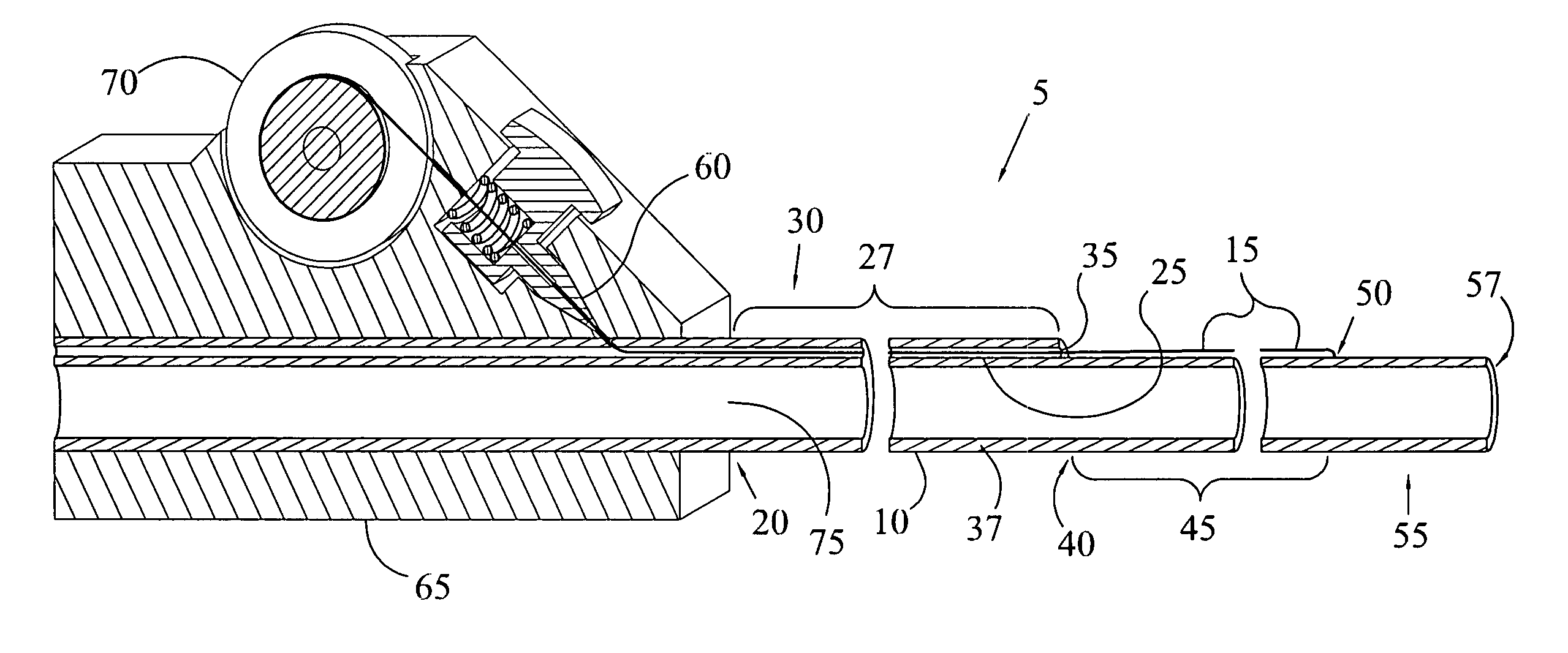
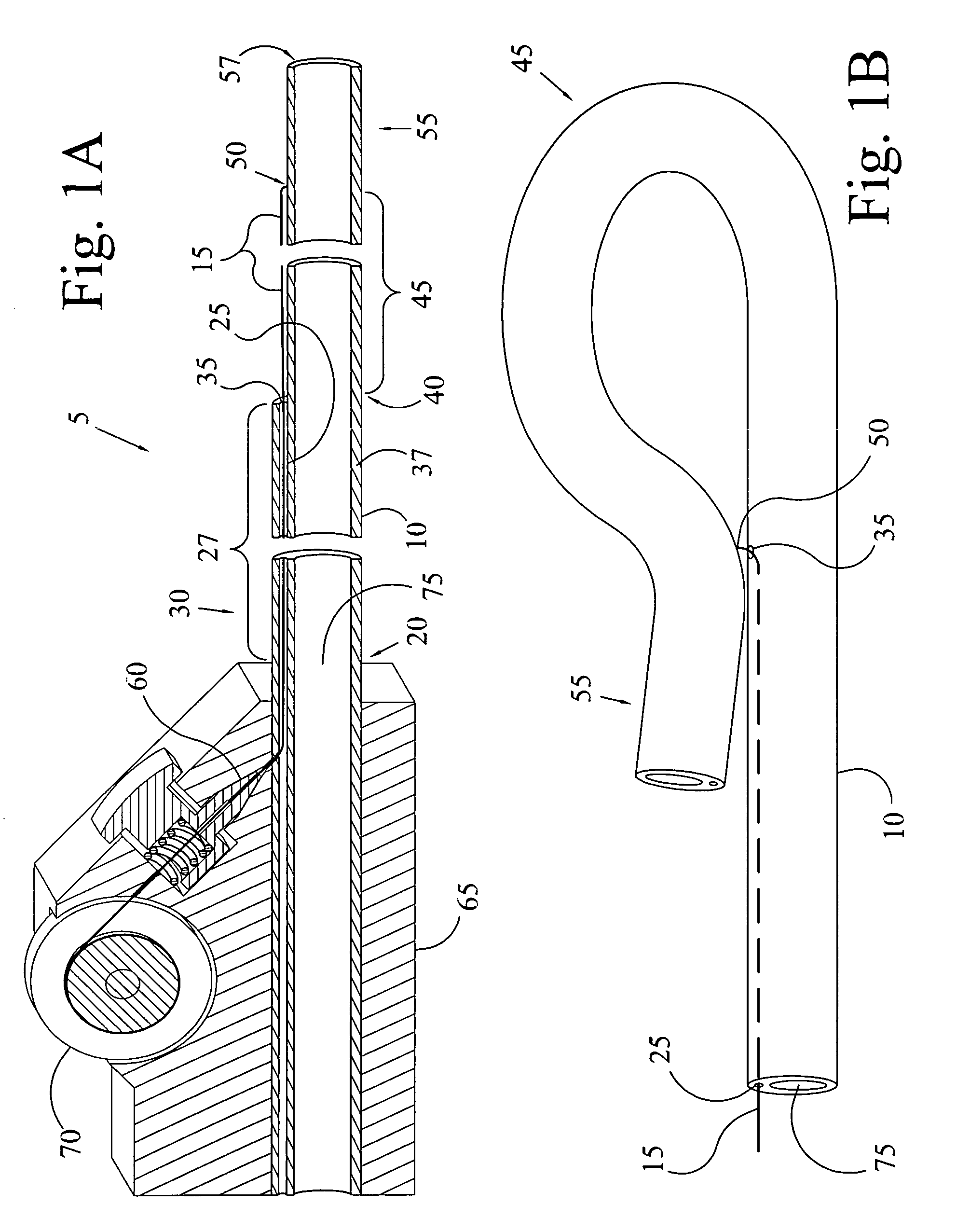
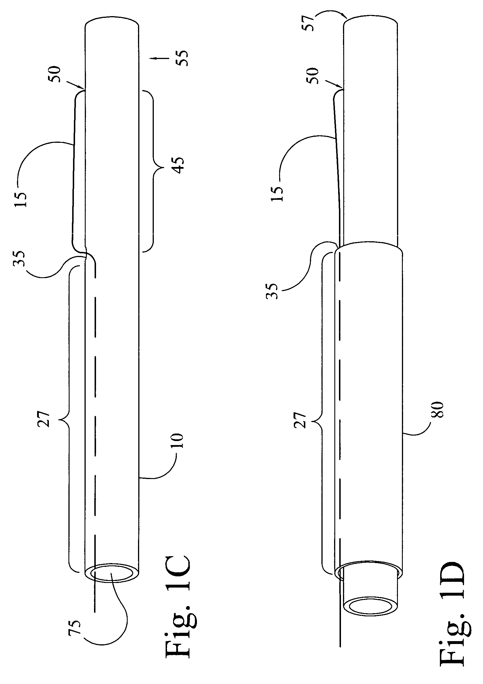
[0065]The present invention is an access guide catheter that is low profile to allow access via a radial artery approach and provides support for passage of an interventional catheter such as a stent system by forming a closed loop conformation. Larger catheters can also be formed using the present invention for other tubular vessels and applications not limited by vessel size. The low profile is accomplished by providing a very thin fiber that attaches near the distal region of the catheter and forces it to form a closed loop in the loop region of the catheter but still provide a great deal of support even though the wall thickness is thin and flexible. Support is provided by the closed loop which does not open up or back out of an ostium as tension is applied to the access guide catheter and an interventional catheter is being advanced within it.

[0066]FIG. 1A shows one embodiment of the access guide catheter (5) of the present invention. It is a 5-6 F catheter intended to fit well...


PUM


Abstract

The Access guide catheter provides passage for therapeutic and diagnostic devices through vessels or conduits that return substantially in a direction from which they originated. One application is for delivery of therapeutic catheters to the carotid or cerebral arteries via access from the radial or brachial artery. The guide catheter enters the aorta from one of the great vessels, forms a closed loop in the aorta, and is directed back into a great vessel in an opposed direction. The distal portion of the guide catheter is advanced into the great vessel for support. Further support is attained by providing tension to the proximal shaft of the guide catheter. Flexibility of the guide catheter allows diagnostic angiograms to be performed prior to delivery of a therapeutic catheter or device.

Description

CROSS REFERENCE TO RELATED APPLICATIONS[0001]This application claims the benefit of provisional patent applications: 61 / 010,753 filed 11 Jan. 2008, 61 / 065,919 filed 15 Feb. 2008, 61 / 067,879 filed 3 Mar. 2008, 61 / 070,398 filed 21 Mar. 2008 and 61 / 190,088 filed 26 Aug. 2008 all by the inventor Joseph M. Thielen.BACKGROUND OF THE INVENTION[0002]1. Field of Invention[0003]This invention relates to an interventional catheter that is placed within vessels of the body to provide access and support for another interventional catheter having passage within it and delivered to the site of a lesion.[0004]2. Description of Prior Art[0005]Access to coronary arteries, carotid arteries, and some peripheral vessels of the body for percutaneous therapeutic and diagnostic catheters is often made via guide catheters that are placed through introducer sheaths which are positioned into vessels that are most easily accessed from outside of the body. Such access sites include the common femoral artery, th...

Claims


Application Information

Patent Timeline
Patent Type & Authority Patents(United States)
IPC IPC(8): A61M31/00
CPCA61M25/0138A61M25/0147A61M25/0662A61M25/0152A61M2025/0161A61M2025/0163
Inventor THIELEN, JOSEPH MICHAELDRASLER, WILLIAM JOSEPH
Owner THIELEN JOSEPH MICHAEL
Learn More