Rotor for a direct current drive motor and a method for producing the same

a direct current drive motor and rotor technology, applied in the direction of rotating parts of magnetic circuits, magnetic circuit shapes/forms/construction, cooling/ventilation arrangement, etc., can solve the problems of high cost, poor integrity, excessive vibration, etc., and achieve good integrity, easy production, and cost-effective

Active Publication Date: 2011-10-04
ZHONGSHAN BROAD OCEAN
View PDF6 Cites 11 Cited by
  • Summary
  • Abstract
  • Description
  • Claims
  • Application Information

AI Technical Summary

Benefits of technology

In view of the above-described problems, it is an objective of the invention to provide an external rotor for a direct current drive motor that is light, cost-effective and easy to produce, features good integrity, and prevents excessive vibration during operation.
It is another objective of the invention to provide a method for producing an external rotor for a direct current drive motor that is a complex production process, and the external rotor produced thereby features good integrity and low cost.
Advantages of the external rotor according to the invention include the following:1) it is light, cost-effective and easy for production;2) it features good integrity; and3) it can act as a buffer and is capable of reducing excessive vibration in operation.
Advantages of the method for producing an external rotor for a direct current drive motor include the following:1) it is a complex production process; and2) the external rotor produced thereby features good integrity and is low cost.

Problems solved by technology

However, some of the problems encountered with conventional external rotors are that they are heavy, expensive and difficult to produce, feature poor integrity, and often generate excessive vibration during operation.
Moreover, disadvantages of conventional methods for producing external rotors include complexity of production process, poor integrity of rotor components, and high cost.

Method used


Image

  • Rotor for a direct current drive motor and a method for producing the same
  • Rotor for a direct current drive motor and a method for producing the same
  • Rotor for a direct current drive motor and a method for producing the same

Examples


Embodiment Construction

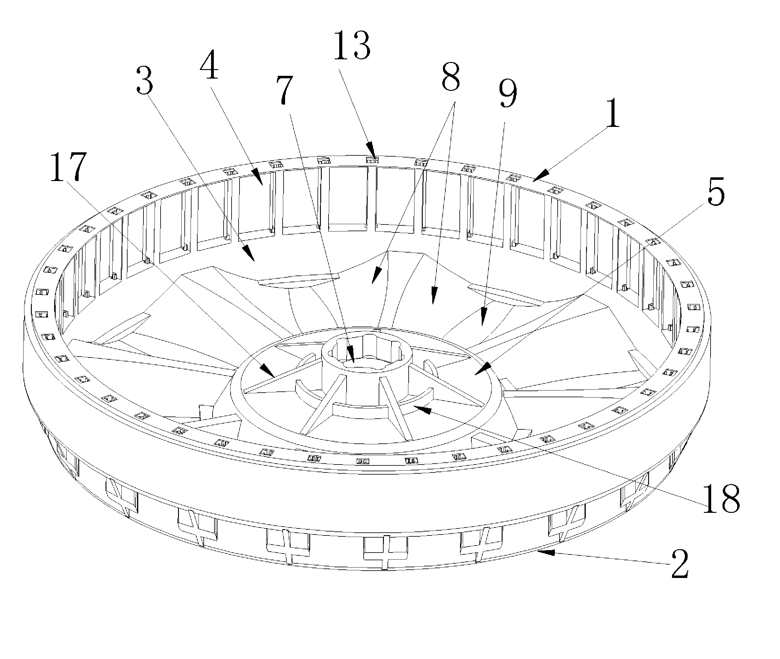
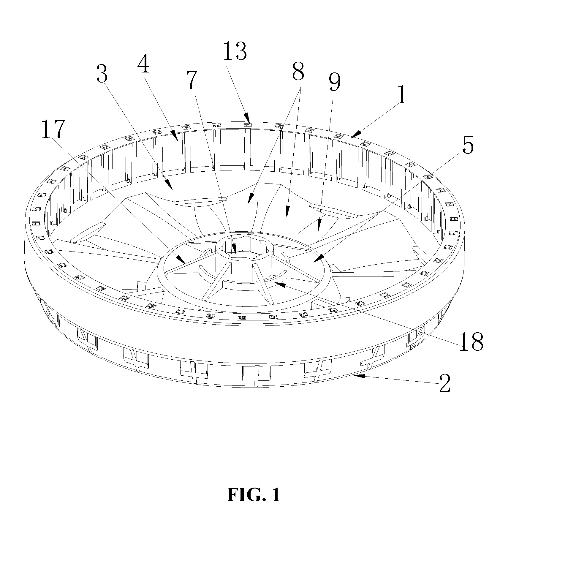
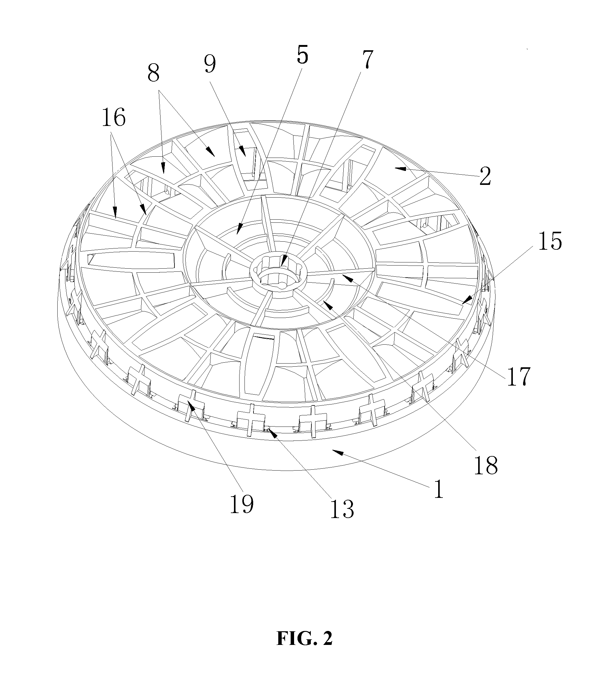
As shown in FIGS. 1-7, an external rotor for a direct current drive motor of the invention comprises a side wall 1, an end cover 2, a cavity 3, an opening 4, a base 5, a magnetic tile 6, a center hole 7, and a magnetic yoke shell 12.

The end cover 2 is disposed at the bottom of the side wall 1, and both of them are integrally formed by injection molding.

The cavity 3 is formed between the side wall 1 and the end cover 2.

The opening 4 is disposed at the top of the housing.

The base 5 is disposed at the center of the end cover 2, and is connected to the side wall 1 via multiple wind wheels 8.

An air inlet 9 is disposed between adjacent wind wheels 8. The thickness of the wind wheel 8 reduces gradually from the center thereof, so that axial airflow is generated as the rotor rotates forwardly or reversely. Each of the wind wheels 8 is in a shape of an inverted V. All the wind wheels 8 are distributed circumferentially, and the number thereof is between 2 and 60.

The wind wheels 8 are connect...


PUM

PropertyMeasurementUnit
thicknessaaaaaaaaaa
magneticaaaaaaaaaa
structural strengthaaaaaaaaaa

Abstract

An external rotor for a direct current drive motor with a side wall, an end cover, a cavity, an opening, a base, a magnetic tile, a center hole, and a magnetic yoke shell. A method for producing an external rotor for a direct current drive motor by integrally forming by injection molding a magnetic yoke shell and multiple magnetic tiles; forming a side wall on said magnetic yoke shell and an end cover at the bottom of said side wall; forming a base at the center of said end cover; and integrally forming by injection molding said base and a rotating spline.

Description

CROSS-REFERENCE TO RELATED APPLICATIONSPursuant to 35 U.S.C. §119 and the Paris Convention Treaty, this application claims the benefit of Chinese Patent Application No. 200810219778.6 filed on Dec. 3, 2008, the contents of which are incorporated herein by reference.BACKGROUND OF THE INVENTION1. Field of the InventionThe invention relates to a rotor, and more particularly to an external rotor for a direct current drive motor and a method for producing the same.2. Description of the Related ArtElements of conventional external rotors for direct current drive motors include a side wall, an end cover, a cavity, an opening, a magnetic conductive housing, and a magnetic tile. Generally, the end cover is disposed at the bottom of the side wall, the cavity is formed between the side wall and the end cover, the magnetic conductive housing is disposed on the side wall, and the magnetic tile is disposed on the inner wall of the magnetic conductive housing.However, some of the problems encounte...

Claims


Application Information

Patent Timeline
Patent Type & Authority Patents(United States)
IPC IPC(8): H02K9/00H02K1/04
CPCH02K1/2786H02K1/30Y10T29/49012H02K9/06H02K15/12H02K1/32H02K1/2791H02K9/04H02K21/22
Inventor ZHANG, XU
Owner ZHONGSHAN BROAD OCEAN
Why Eureka
Try Eureka