Method for charging battery module in multiple stages

a battery module and charging method technology, applied in the field of charging a smart battery module, can solve the problems of reducing the lifespan of parallelly connected battery cell sets, battery charging, and risk of overcharging the battery, and achieve the effect of reducing the charging curren

Active Publication Date: 2011-10-04
COMPAL ELECTRONICS INC
View PDF6 Cites 6 Cited by
  • Summary
  • Abstract
  • Description
  • Claims
  • Application Information

AI Technical Summary

Benefits of technology

[0010]Accordingly, the present invention is directed to a method for charging a battery module in multiple stages, in which by detecting voltage variations of each parallelly-connected battery cell set in the battery module, and reducing a charging current thereof when the voltage of the parallelly-connected battery cell set reaches a safety value for a current difference value, so as to protect the parallelly-connected battery cell sets from over charging.
[0011]The present invention is directed to a method for charging a battery module in multiple stages, in which by detecting voltage variations of each parallelly-connected battery cell set of the battery module, and suitably adjusting a charging current thereof when the voltage of the parallelly-connected battery cell set reaches a safety value, the parallelly-connected battery cell set then may be protected from over charging.
[0023]In the present invention, by voltage control or current control, a constant current charging is applied for charging the battery module in an initial charging stage, and when the voltage of one of the parallely-connected battery cell sets reaches the safety value or the overall voltage of the battery module itself reaches a rated voltage thereof, the constant voltage charging is applied and the charging current is greatly reduced, so as to avoid a safety problem of the battery and prolong the lifespan of the battery.

Problems solved by technology

According to such method, battery charging is only performed according to an overall voltage of the battery module, and can not be adjusted according to the charging state of each parallelly-connected battery cell set.
However, an initial voltage and the charging state of each parallelly-connected battery cell set may be different, and therefore a problem that the battery module is probably still under charging if the voltage of a certain parallelly-connected battery cell set exceeds a safety value (while the overall voltage of the battery module does not exceed the safety value) may be occurred, and such problem not only reduces lifespan of the parallelly-connected battery cell sets, but also leads to a risk of over charging of the battery.
Though the aforesaid method, the problem of over charging on an individual parallelly-connected battery cell set may be solved, it has to take a relatively long time to charge the battery module as the power of the charger is discontinuously supplied.
Moreover, frequent charge and discharge of the battery may reduce the lifespan thereof, which is still not an optimal charging method.

Method used


Image

  • Method for charging battery module in multiple stages
  • Method for charging battery module in multiple stages
  • Method for charging battery module in multiple stages

Examples


first embodiment

The First Embodiment

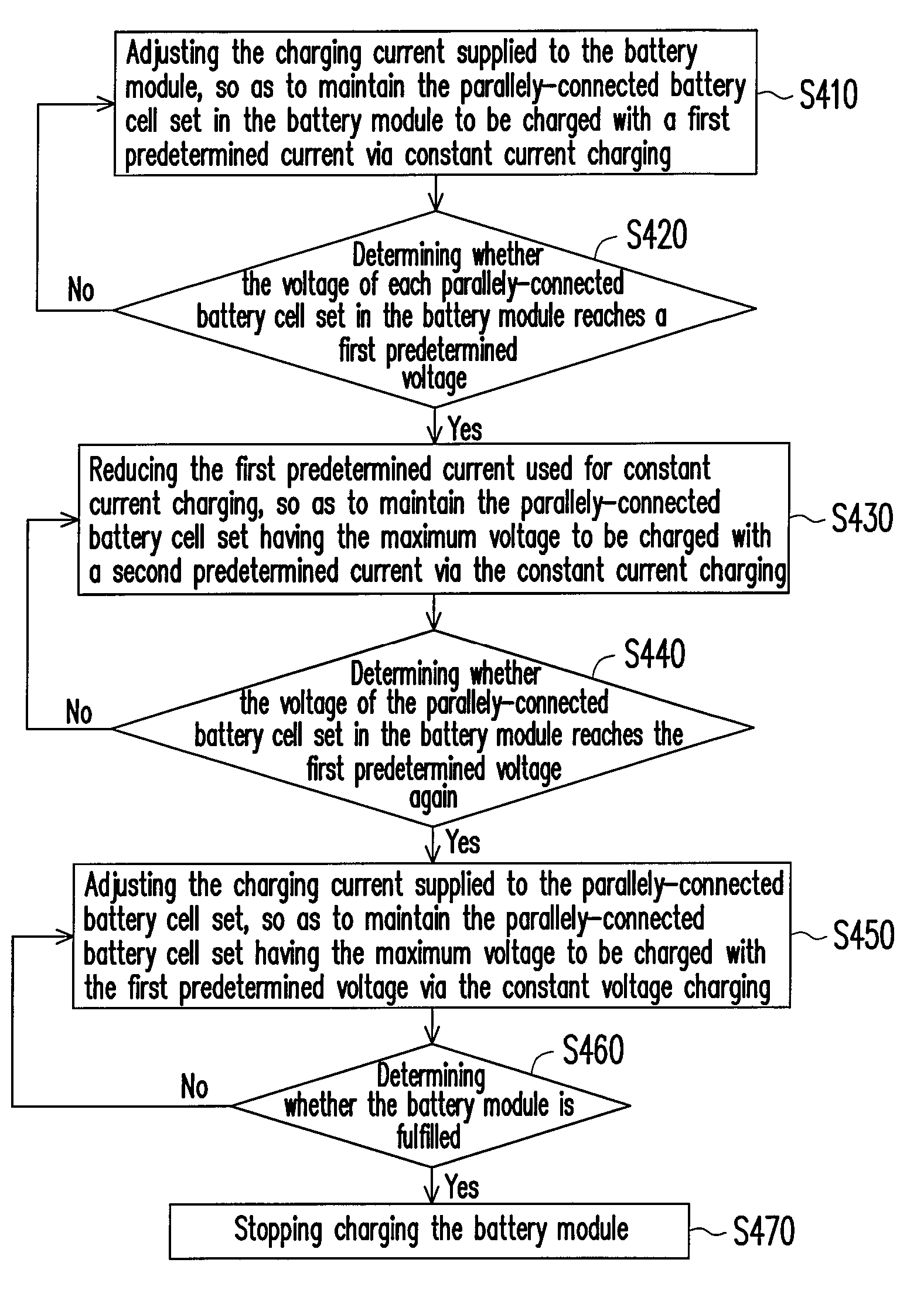
[0046]When the voltage of the battery module is closed to its rated voltage, chargeable places (hole) thereof are greatly reduced, and now if the battery module is still charged with a high current continuously, safety of the battery module cannot be ensured. Accordingly, in an embodiment of the present invention, when the voltage of one of the parallely-connected battery cell sets in the battery module reaches a maximum voltage that the battery module may bear for safe operation, the charging current supplied to the parallely-connected battery cell set is reduced by a certain level, so as to maintain the safety of the battery module.

[0047]FIG. 4 is a flowchart illustrating a method for charging a battery module in multiple stages according to a first embodiment of the present invention. Referring to FIG. 4, in the present embodiment, a battery module including a plurality of parallely-connected battery cell sets is charged through controlling the charging curren...

second embodiment

The Second Embodiment

[0059]Besides the “current control” during charging the battery module as described above, the “voltage control” may also be applied for charging-the battery module, and an embodiment thereof is provided below.

[0060]FIG. 7 is a flowchart illustrating a method for charging a battery module in multiple stages according to a second embodiment of the present invention. Referring to FIG. 7, the battery module including the plurality of parallely-connected battery cell sets is charged through controlling the “charging voltage”, and when the voltage of one of the parallely-connected battery cell sets in the battery module reaches a maximum voltage that the battery module may bear for safe operation, the charging current supplied to the parallely-connected battery cell set is reduced by a certain level, so as to maintain the safety of the battery.

[0061]FIG. 8 is a diagram illustrating a charging curve of a battery module according to a second embodiment of the present i...

third embodiment

The Third Embodiment

[0071]In both two aforementioned embodiments, the charging current is greatly decreased for protecting the battery module when the voltage of the parallely-connected battery cell set reaches the rated voltage. Compared to the aforementioned embodiments, in the present embodiment, the time point for “greatly reducing the charging current” is delayed, namely, when the voltage of the parallely-connected battery cell set reaches the rated voltage, the parallely-connected battery cell set is first charged with the rated voltage via the constant voltage charging, until the charging voltage is gradually decreased to a certain low charging current, and then the charging current is greatly reduced to accelerate charging speed of the battery module.

[0072]FIG. 10 is a flowchart illustrating a method for charging a battery module in multiple stages according to a third embodiment of the present invention. FIG. 11 is a diagram illustrating a charging curve of a battery module...


PUM


Abstract

A method for charging a battery module including a plurality of parallelly-connected battery cell sets in multiple stages is provided. In the present invention, a constant current charging is applied for charging the battery module in an initial stage of charging through the method of voltage control or current control. Then, the charging current is lowered substantially to reduce the charging speed when the voltage of one of the battery cell sets exceeds a safety value or a total voltage of the battery module itself reaches a rated voltage. Accordingly, a safety problem of the battery can be avoided and battery life can be prolonged.

Description

CROSS-REFERENCE TO RELATED APPLICATION[0001]This application claims the priority benefit of Taiwan application serial no. 96121485, filed on Jun. 14, 2007. The entirety the above-mentioned patent application is hereby incorporated by reference herein and made a part of specification.BACKGROUND OF THE INVENTION[0002]1. Field of the Invention[0003]The present invention relates to a method for charging a battery module. More particularly, the present invention relates to a method for charging a smart battery module in multiple stages.[0004]2. Description of Related Art[0005]With increasing performance of a processor, increasing of application programs, and advancing of graphic functions, power requirement of a portable computer is increased accordingly. To cope with the power requirement of the portable computer during normal operation thereof, a plurality of parallelly-connected battery cell sets is generally connected in serial and assembled in a battery module, so as to provide suff...

Claims


Application Information

Patent Timeline
Patent Type & Authority Patents(United States)
IPC IPC(8): H02J7/00
CPCH01M10/441H02J7/0073H02J7/0022H02J7/0071Y02E60/10H02J7/0013
Inventor KUNG, SHAO-TSUCHEN, CHIA-CHANGCHUANG, CHIH-TARNG
Owner COMPAL ELECTRONICS INC
Why Eureka
Try Eureka