Computerised cortex boundary extraction from MR images

a computerised cortex and boundary extraction technology, applied in image enhancement, instruments, nuclear engineering, etc., can solve the problem of poor approximation of the second boundary not very far into the tight fold, and achieve the effect of high degree of certainty, high complexity and reliable reconstruction

Inactive Publication Date: 2011-10-04
AALBORG UNIV
View PDF8 Cites 24 Cited by
  • Summary
  • Abstract
  • Description
  • Claims
  • Application Information

AI Technical Summary

Benefits of technology

[0013]It is therefore the objective of the invention to provide an improved, robust, and accurate method for automatically modelling the boundary of a folded structure in a digital image. Especially, the purpose is a more accurate modelling of the folds even if the folds are not distinct in the image. Furthermore, it is an objective of the invention to provide an improved, robust, and accurate method for automatically calculating outer boundary, and optionally also the inner boundary, of the cortex on the basis of datasets representing MR images.
[0018]Another remarkable difference between the method as disclosed in Xu's dissertation and the invention should be noted. According to the invention, the deformable curve or surface is deformed convergently towards the second boundary, which implies that the curve converges at the boundary, for example the outer boundary of the grey matter. In contrast, in Xu's method, the outer surface of the grey matter is not found but a central layer inside the grey matter is used, which implies an uncertainty in the calculated thickness of the cortex. In contrast thereto, the approximate finding of the boundary of the grey matter, in accordance to the invention, yields a high degree of certainty for the calculated cortical thickness and volume.
[0024]Alternatively, a different gradient vector force field may be applied, where this gradient is calculated by convolving the gradient image with a Gaussian kernel, and thereby extending the gradient information. The direction vectors are then obtained by calculating the first order partial derivative of the extended gradient. The extension of the gradient information can be done in a multi-scale fashion, so that the information of the sharp image edge is not lost. However, by calculating a vector field in this way, a direction vector is not guaranteed to be present at all positions in the image, only within the “capture range” of the Gaussian kernel.
[0027]In a further embodiment, the method comprises providing a step size for the iterative deformation of the curve / surface, where the step size is calculated as the length of the resulting vector of the vector force field scaled by a dynamic factor depending on the distance to the second boundary. The dynamic factor may be dependent on the evidence of the second boundary, where this evidence may be based on the image gradient or a classification of the image intensities. Thus, the step size decreases in the vicinity of the second boundary. This is one of the ingredients that ensures convergence of the calculation.
[0031]Alternatively, a binary classification may be employed. However, in contrast to a binary classification, the fuzzy or probabilistic algorithms have the advantage that more information is retained. As several objects may span a single voxel, the exact location of the border between the objects must be interpolated. The binary segmentation assigns every voxel to a single object, and thus discards information which can be used for obtaining an accurate sub-voxel delineation of an edge through interpolation.

Problems solved by technology

Starting with an initial curve / surface in the first or second object, for example a curve / surface that in a fold-embracing manner resembles the first boundary, and using a vector force field, for example comprising a gradient vector field, but not a normal vector field for the iterative deformation of this curve / surface towards the second boundary may result in a poor approximation of the second boundary not extending very far into the tight fold, simply because a gradient vector field during the iteration pulls the deformed curve / surface out of the fold towards the third object.

Method used


Image

  • Computerised cortex boundary extraction from MR images
  • Computerised cortex boundary extraction from MR images
  • Computerised cortex boundary extraction from MR images

Examples


Embodiment Construction

[0057]The method according to the invention can be used as a general method for extraction of contours from images, for example from grey scale images with object contours having blurry and / or faint borderlines. However, as an example, the method according to the invention will be explained in detail for the extraction of the cerebral cortex from sets of magnetic resonance (MR) images. It is assumed that images have been taken with MR as slices of a three dimensional volume containing the brain of a human being. The applied set of images in the form of digitised data will be termed MR volume in the following.

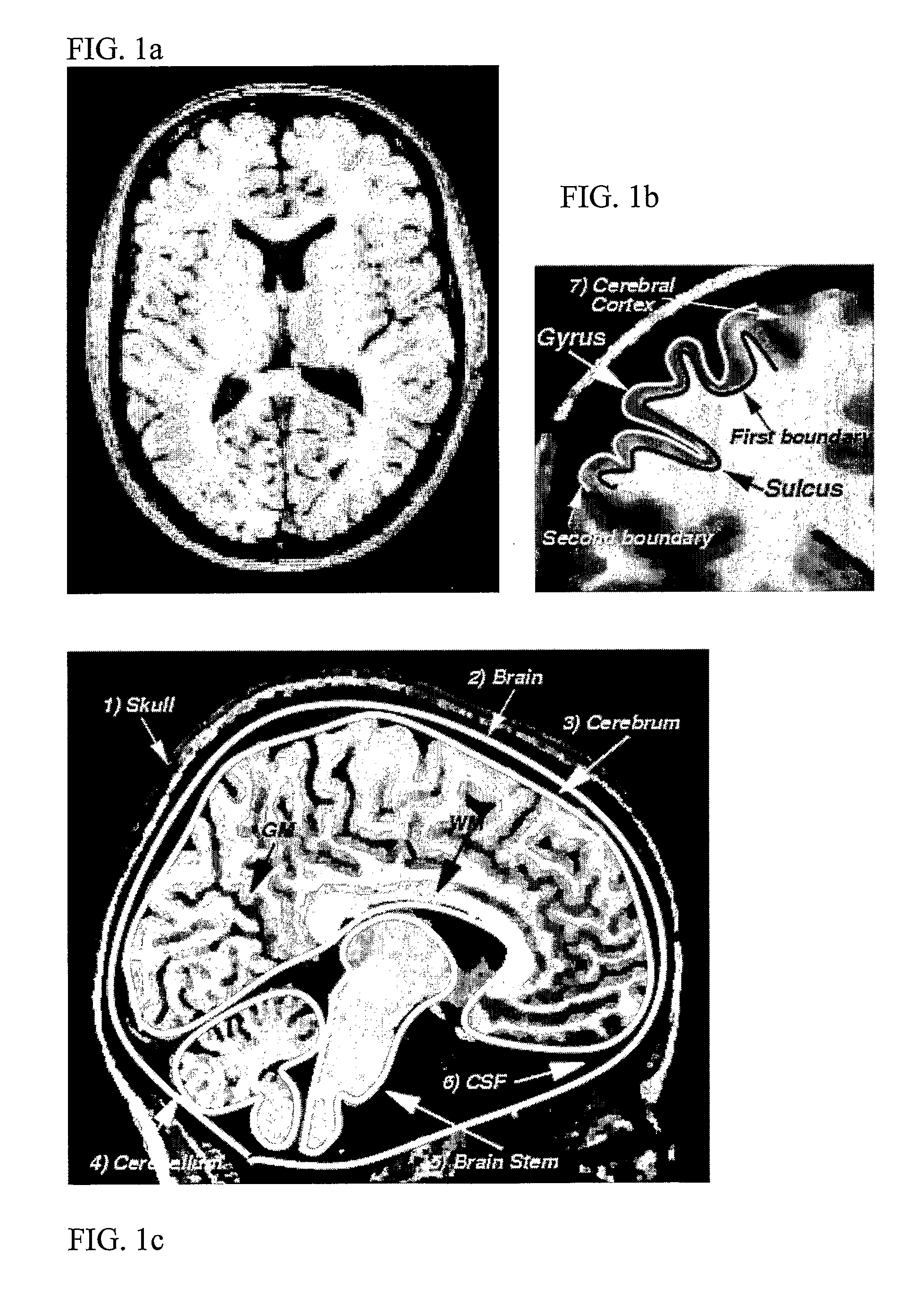
[0058]FIG. 1 illustrates dataset from an MR volume in the form of digitised images that show slices of a brain taken at different angles (transversal and sagittal) of a human being. The images show with highlight of roughly approximated boundaries the surrounding skull 1, inside which the brain 2, comprising the cerebrum 3, the cerebellum 4 and the brain stem 5, is embedded in a...


PUM


Abstract

Method for processing digital images, such as magnetic resonance images of a brain. The images contain a first object, for example the cerebrum white matter, a second object, for example the cerebral cortex, and a third object, for example the cerebrospinal fluid. The method involves providing a digital dataset representing a deformable curve or surface that in an initial state approximates the boundary between the first object and the second object. Further, a vector force field is provided that for each point on the deformable curve or surface defines a direction from the point approximately towards the second boundary between the second and the third object, and this vector force field is applied for iteratively deforming the deformable curve or surface convergently towards the second boundary. In order to reconstruct a folded structure of the second object, for example the cortex, the vector force field also involves a normal vector field with a vector normal or approximately normal to the deformable curve or surface for each point on the deformable curve or surface.

Description

[0001]This application claims the benefit of U.S. Application Ser. No. 60 / 570,493, European Application No. 04011386.2 filed May 13, 2004 and PCT / DK2005 / 000320 filed May 13, 2005, which are hereby incorporated by reference in their entirety.FIELD OF THE INVENTION[0002]The present invention relates to a method for boundary extraction in images, for example MR images of a brain.BACKGROUND OF THE INVENTION[0003]Several neurodegenerative diseases, such as Alzheimer's disease, cause atrophy of the cerebral cortex. Measurements of cerebral cortical thickness and volume can be used in the quantification and location of atrophy. While it is possible to measure the thickness of the cerebral cortex manually from magnetic resonance (MR) images, partial volume effects (PVE), orthogonality problems, large amounts of manual labour and operator bias makes it difficult to make measurements on large patient populations. Automatic quantification and localisation of atrophy is a highly desirable goal,...

Claims


Application Information

Patent Timeline
Patent Type & Authority Patents(United States)
IPC IPC(8): G06K9/00G06T5/00G06V10/46
CPCG06K9/48G06T7/0083G06T7/0089G06T17/20G06T2207/10088G06T2207/20116G06T2207/30016Y10S128/922G06T7/12G06T7/149G06V10/46
Inventor ESKILDSEN, SIMON FRISTEDULDAHL, MARKOSTERGAARD, LASSE RIISPRISAK, ANDERS
Owner AALBORG UNIV
Why Eureka
Try Eureka