Method and apparatus for the cleaning of components of a power plant by the injection of a medium and measuring device for measuring the degree of purity of the medium

a technology for power plants and components, applied in the direction of cleaning hollow objects, cleaning using liquids, instruments, etc., can solve the problems of affecting the efficiency of turbines, damage to plant parts, and damage in this case, so as to avoid relative movements, reduce the removal time necessary for restoring the normal operation of the plant, and avoid water loss

Active Publication Date: 2011-10-18
SIEMENS ENERGY GLOBAL GMBH & CO KG
View PDF20 Cites 3 Cited by
  • Summary
  • Abstract
  • Description
  • Claims
  • Application Information

AI Technical Summary

Benefits of technology

[0019]The invention in this case proceeds from the consideration that, for as uninterrupted a cleaning process as possible for, in particular, steam-carrying plant parts of a power plant, the cleaning process should be carried out in circulatory operation. In this case, as medium, steam condensed in the condenser is routed continuously in a closed flow circuit through one or more plant parts to be cleaned, a testing of the medium for its degree of purity being carried out in at least one operational plant part. It thereby becomes possible to clean without interruption until the required freedom from particles is achieved, with the result that, in turn, the cleaning times are reduced considerably. Whether the required freedom from particles is present is detected by means of a measuring device arranged directly in an operational plant part. By means of closed steam cleaning the cleaning process is independent of the demineralized water generation capacity or demineralized water storage capacity. There is also no need for a rapid afterfeed of the demineralized water, since the closed cleaning process can be carried out virtually without any water loss.
[0038]The advantages achieved by means of the invention are, in particular, that, by steam cleaning in circulatory operation during the condensation of the steam in the condenser and therefore when the plant is condensation operation, a testing of the degree of purity of the steam in the operational steam line becomes possible, and cleaning can be carried out virtually without any water loss. The cleaning process is thus made possible virtually independently of the demineralized water generation capacity, storage capacity and afterfeed. Due to cleaning in circulatory operation, complicated sound protection measures may be dispensed with because of the extremely low-noise process. Moreover, merely simple and only few blow-out facilities are required, and therefore the removal time necessary for restoring the normal operational plant state is markedly reduced.

Problems solved by technology

Such solid particles may lead to damage to the plant parts, such as, for example, the turbine.
Damage in this case occurs particularly on the blading and the labyrinth seals of the turbine.
This leads to material stripping and blade toughening and consequently to the impairment of turbine efficiency.
In so far as the solid particles are braked by the turbine and they remain in the turbine, there is the risk that they lead to roughenings on the blading and possibly form deposits in the labyrinth seals.
These deposits may damage or destroy sealing elements or other components.
Even with the greatest care during installation work, the situation cannot be certainly be avoided where dust, sand, installation objects and installation waste are left behind in steam-carrying components or plant parts of the plant.
Thus, for example, before every first steam pulse of a steam turbine, the steam-carrying boiler regions and the steamlines are freed of particles which may lead to damage and / or to an impairment of efficiency.
Furthermore, complicated blow-out facilities are necessary in order to ensure a rapid afterfeed of demineralized water into the condensate system and in order to limit the sound emissions occurring during atmospheric steam blow-out to the required sound levels.
For example, for this purpose, silencers are used, or water injection into the steam takes place and therefore leads to an additional water demand.
Also, the conventional circulatory cleanings cannot be carried out uninterruptedly, since the assessment of the freedom of the steam from particles is not possible online in high temperature and pressure ranges.

Method used


Image

  • Method and apparatus for the cleaning of components of a power plant by the injection of a medium and measuring device for measuring the degree of purity of the medium
  • Method and apparatus for the cleaning of components of a power plant by the injection of a medium and measuring device for measuring the degree of purity of the medium
  • Method and apparatus for the cleaning of components of a power plant by the injection of a medium and measuring device for measuring the degree of purity of the medium

Examples


Embodiment Construction

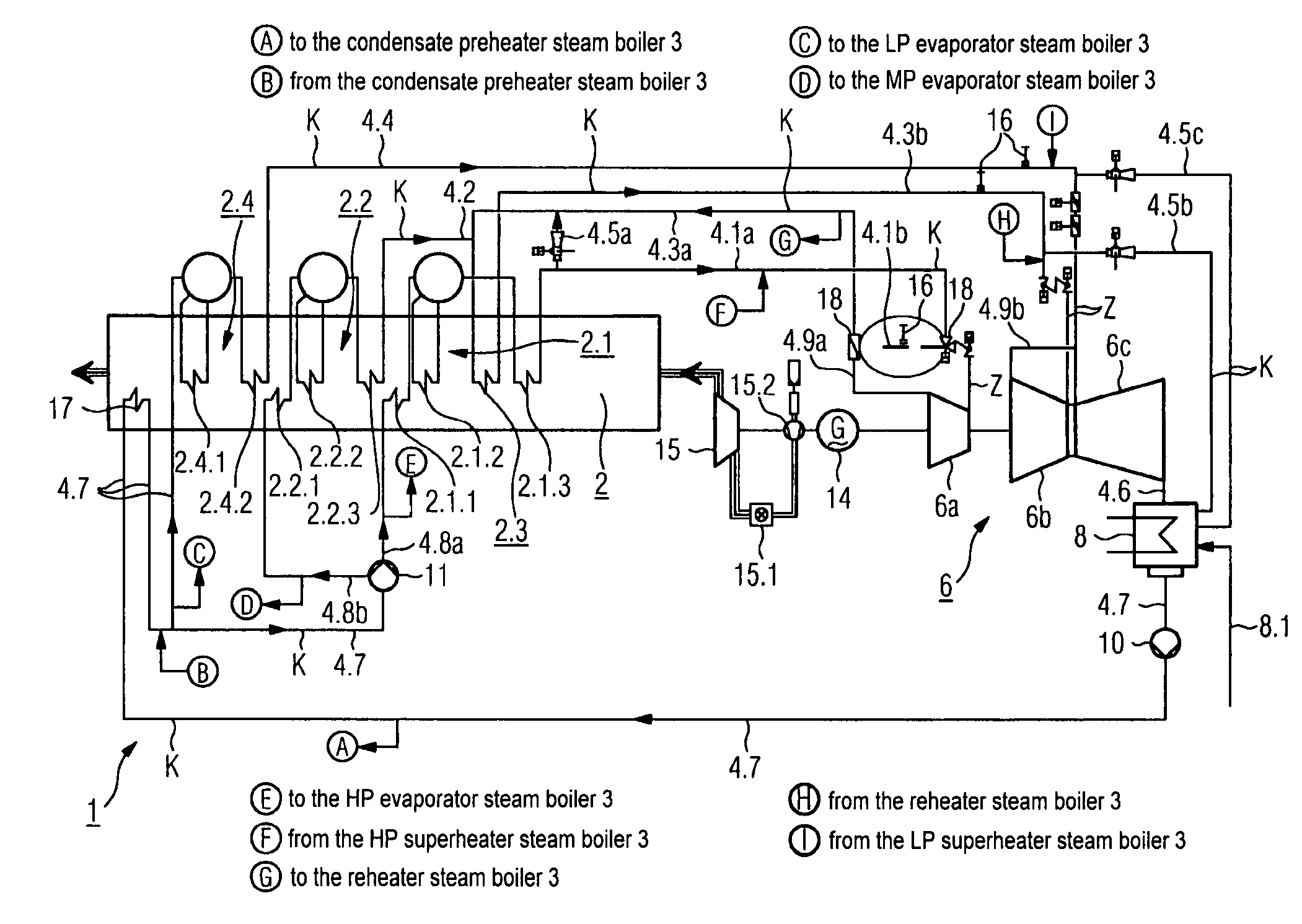
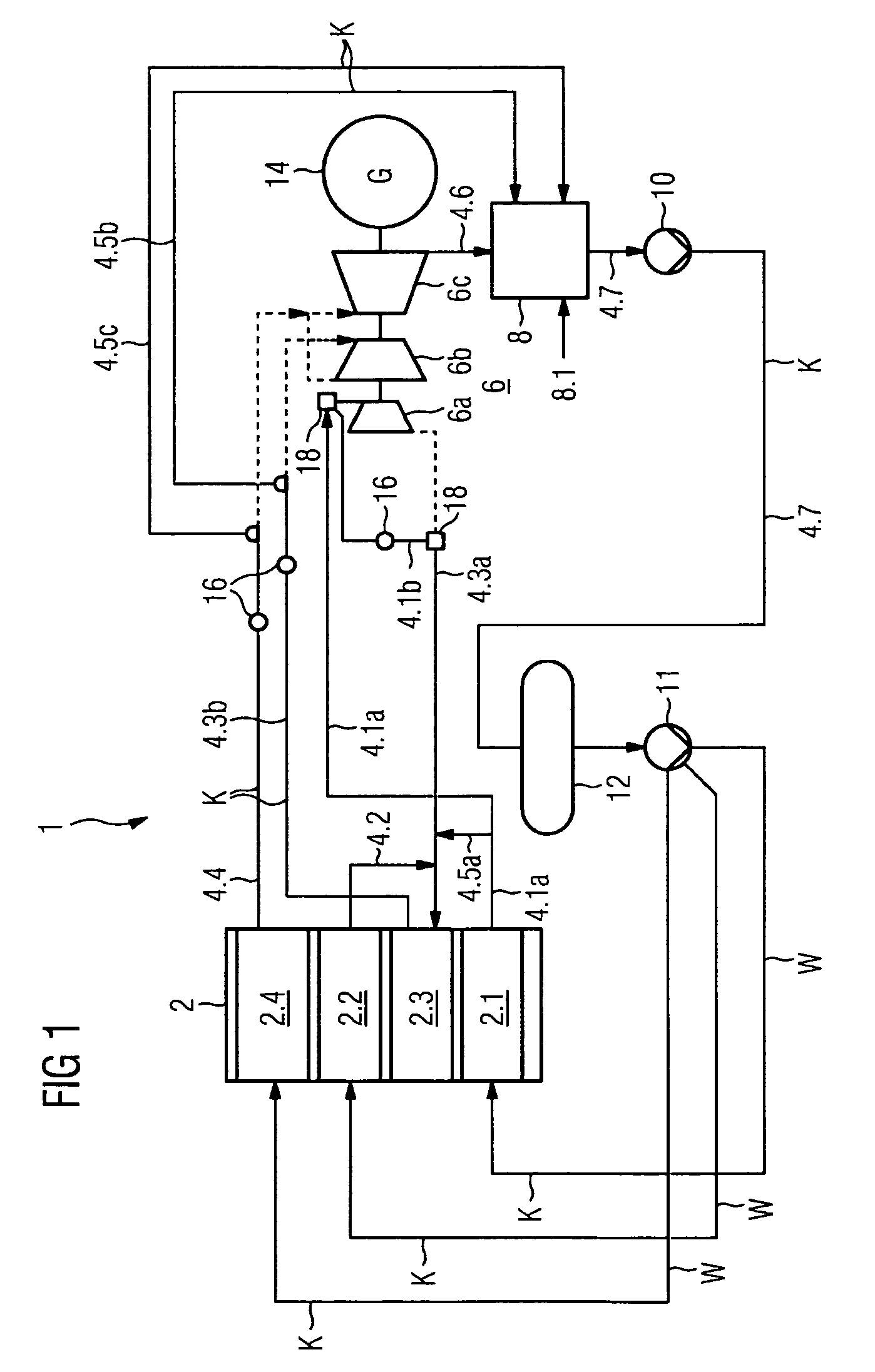
[0045]FIG. 1 shows a closed flow circuit K for cleaning the plant parts of a power plant 1. The closed flow circuit K is identified by a double line.

[0046]The power plant 1 comprises a steam boiler device 2 with a plurality of pressure stages 2.1 to 2.4, for example consisting of a high-pressure part, of a medium-pressure part, of a low-pressure part and of a reheater, which feed a steam turbine unit 6 via steam lines 4.1a, 4.3b and 4.4 when the power plant 1 is in normal operation. The components of the power plant 1 which are bypassed in the cleaning process are identified by a dashed line.

[0047]In normal operation, a steam line 4.6 goes from the steam turbine unit 6 to a recirculation device which comprises a condenser 8 and a condensate pump 10, in order to supply the water obtained from the condensed steam to the steam boiler device 2 again via a return line 4.7. Water losses are compensated via the supply line 8.1 and are added to the feed water tank 12 via the condenser 8 and...


PUM

PropertyMeasurementUnit
temperatureaaaaaaaaaa
pressureaaaaaaaaaa
angleaaaaaaaaaa

Abstract

The invention relates to a method for cleaning plant components of a power station, wherein a medium is continuously passed through one or more plant components for cleaning a closed circuit and a check of the medium for degree of purity is carried out in at least one operating plant component.

Description

CROSS REFERENCE TO RELATED APPLICATIONS[0001]This application is the US National Stage of International Application No. PCT / EP2006 / 067791, filed Oct. 26, 2006 and claims the benefit thereof. The International Application claims the benefits of European application No. 05027687.2 filed Dec. 16, 2005, both of the applications are incorporated by reference herein in their entirety.FIELD OF INVENTION[0002]The invention relates to a method for the cleaning of components of a power plant, in particular of a steam turbine plant or of a gas and steam turbine plant. It relates, furthermore, to an apparatus for the cleaning of components of a power plant, into which apparatus a medium, in particular a vaporous medium, is introduced, in particular injected. It relates, further, to a measuring device for measuring the degree of purity of the medium and for use in the apparatus for cleaning the components.BACKGROUND OF THE INVENTION[0003]The purity of the steam in the operation a power plant has...

Claims


Application Information

Patent Timeline
Patent Type & Authority Patents(United States)
IPC IPC(8): B08B7/04B08B9/093
CPCB08B9/00B08B9/032B08B9/0321G01N1/2247G01N15/0606G01N33/18
Inventor LONNE, ROLFELSEN, JANKARL, ROBERT
Owner SIEMENS ENERGY GLOBAL GMBH & CO KG
Why Eureka
Try Eureka