Carrier body for components or circuits

Active Publication Date: 2011-10-18
CERAMTEC
View PDF33 Cites 13 Cited by
  • Summary
  • Abstract
  • Description
  • Claims
  • Application Information

AI Technical Summary

Benefits of technology

[0003]According to the prior art, planar structures are constructed for dissipating heat from modules of power electronics, which structures dissipate the heat diffusing from a heat source (active or passive electrical components) via numerous interlayers (solders, conductive pastes, adhesive compounds, metallizations) into an electrically nonconductive, uniformly shaped, simple geometric body (disc, rectangular substrate). Although the geometry of the individua

Problems solved by technology

Although the geometry of the individual components is simple, the entire layer construction is complicated and requires consecutive application of a very wide variety of processes which are susceptible to faults, such as adhesive bonding, pressing, screwing and also, to a limited extent, soldering.
Each interface of this stacked construction represents a barrier for

Method used


Image

  • Carrier body for components or circuits
  • Carrier body for components or circuits
  • Carrier body for components or circuits

Examples


Embodiment Construction

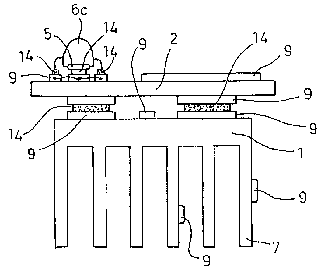
[0036]In one configuration according to the invention, the carrier body is a printed circuit board. The conductor tracks are then applied to the carrier body. The conductor tracks of the printed circuit board can be intimately connected to the carrier body, for example via a thermal process, or metallic conductor tracks can be adhesively bonded thereon or conductive adhesives can be used. It is also possible for combinations of different conductor track types to be used.

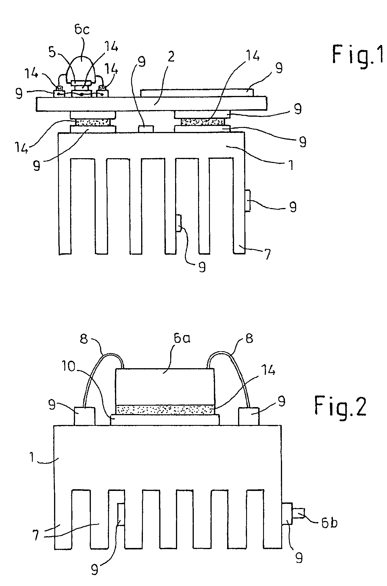
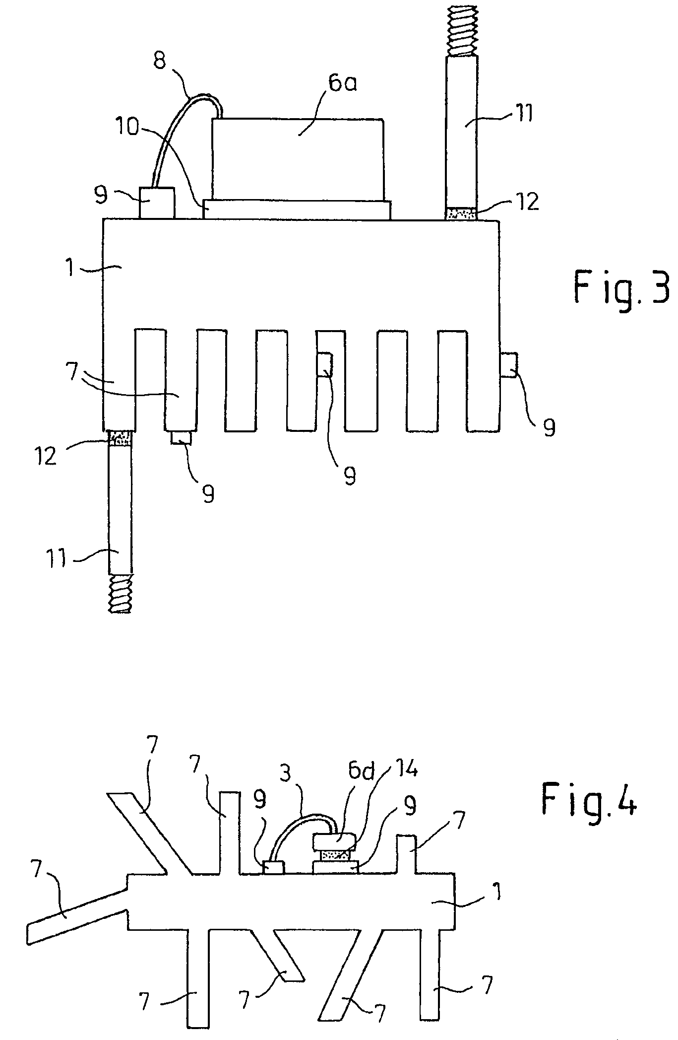
[0037]Preferably, the components have a direct outflow of heat into the carrier body or else into the cooling elements. The components can be connected to the carrier body, for example directly or via one or more layers.

[0038]The terms component elements and components describe the same objects.

[0039]Preferably, the cooling elements are drilled holes, channels, ribs and / or cutouts, to which a cooling medium can be applied.

[0040]The heating or cooling medium can be a gas, such as air, for example, or a liquid, such as...


PUM


Abstract

A carrier body for electrical or electronic component elements or circuits, the carrier body being electrically nonconductive or virtually nonconductive. In order to simplify the carrier body while at the same time providing extremely improved heat dissipation, the invention process that the carrier body is provided integrally with heat-dissipating or heat-supplying cooling elements.

Description

[0001]This application is a §371 of PCT / EP2007 / 052726 filed Mar. 22, 2007 which claims priority from DE 10 2006 013 873.2 filed Mar. 23, 2006, DE 10 2006 055 965.7 filed Nov. 24, 2006 and DE 10 2006 058 417.1 filed Dec. 8, 2006.FIELD OF THE INVENTION[0002]The invention relates to a carrier body for electrical or electronic component elements or circuits, the carrier body being electrically nonconductive or virtually nonconductive.BACKGROUND AND SUMMARY OF THE INVENTION[0003]According to the prior art, planar structures are constructed for dissipating heat from modules of power electronics, which structures dissipate the heat diffusing from a heat source (active or passive electrical components) via numerous interlayers (solders, conductive pastes, adhesive compounds, metallizations) into an electrically nonconductive, uniformly shaped, simple geometric body (disc, rectangular substrate). Although the geometry of the individual components is simple, the entire layer construction is c...

Claims


Application Information

Patent Timeline
IPC IPC(8): H05K7/20F21Y101/00
CPCF21S48/328F21V29/004H01L23/15H01L23/367H01L23/3672H01L23/3731H01L23/3735H01L23/3736H01L23/3737H01L23/552H01L25/162H05K1/0203H01L24/32F21V29/763F21V29/86F21V29/89F21K9/13F21Y2101/02F21Y2105/001H01L25/16H01L33/642H01L33/648H01L2224/32014H01L2224/48091H01L2224/73265H01L2924/01004H01L2924/01005H01L2924/01013H01L2924/01015H01L2924/0102H01L2924/01027H01L2924/01029H01L2924/01033H01L2924/0104H01L2924/01046H01L2924/01047H01L2924/01058H01L2924/01074H01L2924/01077H01L2924/01078H01L2924/01079H01L2924/01082H01L2924/09701H01L2924/13055H01L2924/19041H01L2924/3025H05K1/0284H05K1/0306H05K1/0373H05K2201/0209H05K2201/09045H01L24/48F28F2215/10H01L2924/01006H01L2924/01019H01L2924/01068H01L2924/014H01L2224/32245H01L2224/45139H01L2224/45144H01L2924/07811H01L2924/12041F21V29/71F21V29/713F21V29/75H01L2924/00014H01L2924/1305H01L2924/12042H01L24/45H01L2924/3512H01L2924/00H01L2224/05599H01L33/62F21Y2105/10F21K9/23F21Y2115/10H01L2924/181F21V29/70H01L2924/00011H01L2224/45015H01L2924/207H01L2924/01049H01L23/373
Inventor KLUGE, CLAUS PETER
Owner CERAMTEC
Why Eureka
Try Eureka