Self-propelled forage harvester

a self-propelled, forage harvesting technology, applied in the direction of mowers, applications, agriculture, etc., can solve the problems of the center of gravity may shift, and the inability to drive the forage harvesting machine on the road with good control, so as to optimize the weight distribution of the forage harvester

Active Publication Date: 2011-10-25
CLAAS SELBSTFAHRENDE ERNTEMASCHINEN GMBH
View PDF5 Cites 0 Cited by
  • Summary
  • Abstract
  • Description
  • Claims
  • Application Information

AI Technical Summary

Benefits of technology

[0007]The object of the present invention, therefore, is to provide a self-propelled forage harvester of the type described initially that prevents the aforementioned disadvantages of the known designs of the related art, and to provide a technical solution that makes it possible to optimize the weight distribution of the self-propelled forage harvester without installing additional ballast weights.
[0009]Given that the drive axle of the forage harvester is composed of a center part and axle carrier units that are rigidly flange-connected on the right and left sides of the center part, with each axle carrier unit including integrated wheel gears that are forwardly-positioned in the direction toward the front attachment, the distance between the rear axle and front axle of the drive wheels is advantageously increased, and the drive wheels are located closer to the front attachment, thereby resulting in an optimum weight distribution for the ready-to-operate harvesting machine.
[0013]When both axle bodies are screwed together with the transmission between them in an assembly process, an assembly is produced that is the inventive drive axle and is composed of three independent subassemblies. The three subassemblies are composed of two axle carrier units and the transmission with brakes. One subassembly includes, e.g., the left axle carrier unit, a further subassembly includes the right axle carrier unit, and the third subassembly includes the transmission with the brakes. Due to this rational configuration, production and assembly are simplified, thereby also reducing costs. The compact design of the assembly also results in improved heat dissipation and greater dust protection. The inventive drive axle for the forage harvester, which is formed by the complete assembly, now has a U-shaped or forked design, due to the two axle carrier units with forwardly-positioned wheel gears that are flange-mounted on the right and left ends of the transmission in L-shaped positions. This U-shaped or forked design results from the fact that the short, L-shaped leg of the gear wheel points in the direction of travel and / or the direction of the front attachment. As a result, the drive wheels are shifted forward until they are close to the front attachments. This displacement of the drive wheels results in a more favorable weight distribution.
[0014]In an advantageous refinement of the present invention, the U-shaped or forked drive axle includes a working unit of the forage harvester that is designed as a chopping assembly, thereby making it possible to shift the front wheels further forward.
[0016]Given that the wheel rim of the drive wheel includes the forwardly-positioned wheel gears, the direct inner distance between the wheel gears increases, thereby resulting in more space for the working unit and enabling the working unit to be moved closer to the rigid drive axle.
[0017]A further inventive advantage results from the positioning of the axial offset between the actual rigid axle, which is formed by output shafts of the transmission, which contain the axle bodies, and the output shaft in the forwardly-positioned wheel gears. Given that the drive wheel is offset toward the front relative to the actual rigid axle, it is possible to realize a simple rotary joint on the particular output shaft of the wheel gear and / or wheel shaft. For this purpose, two side walls of the wheel gear include openings, which are located opposite to each other, in parallel, with distance between them, and which receive the output shaft with related bearing and sealing means. In addition, the possibility of installing a tire pressure control system is created, which would allow the drive tires to be easily filled.

Problems solved by technology

When different front attachments are used, e.g., a combine harvester header, a corn header, or a pick-up, the center of gravity may shift, which is unfavorable.
The designs described in publications DD 75 665 and EP 1 151 655 A1 have the disadvantage, however, that a complex design is required in order to realize an optimal center of gravity of the machine.
Due to the high overall mass of the harvesting machine itself and the front attachment that is installed, it is not possible to drive the harvesting machine on the road with good control without additional ballast weights.

Method used


Image

  • Self-propelled forage harvester
  • Self-propelled forage harvester
  • Self-propelled forage harvester

Examples


Embodiment Construction

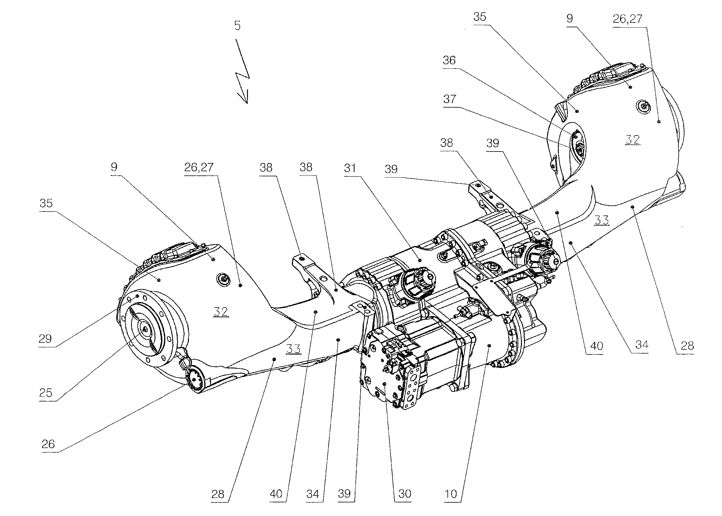
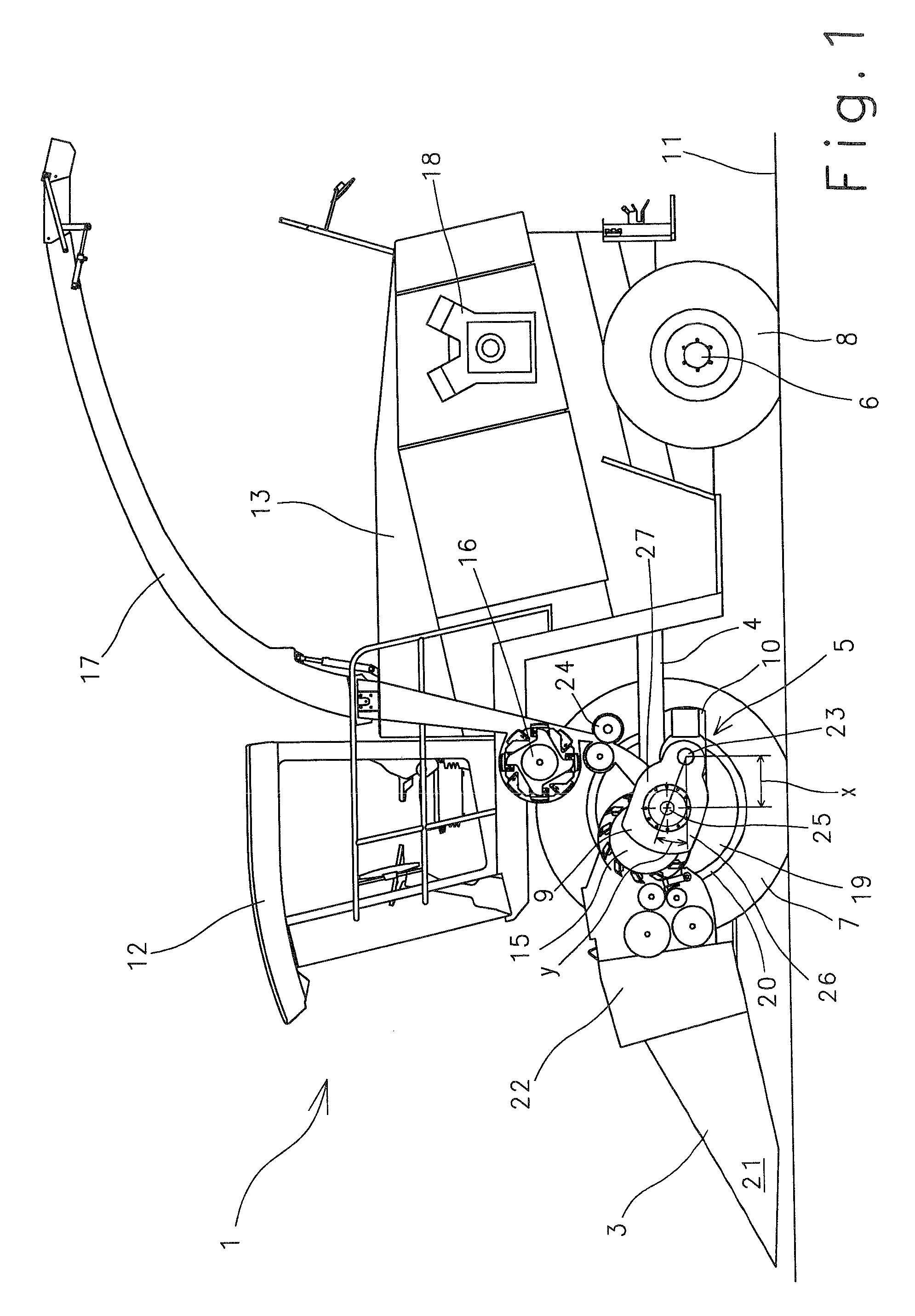
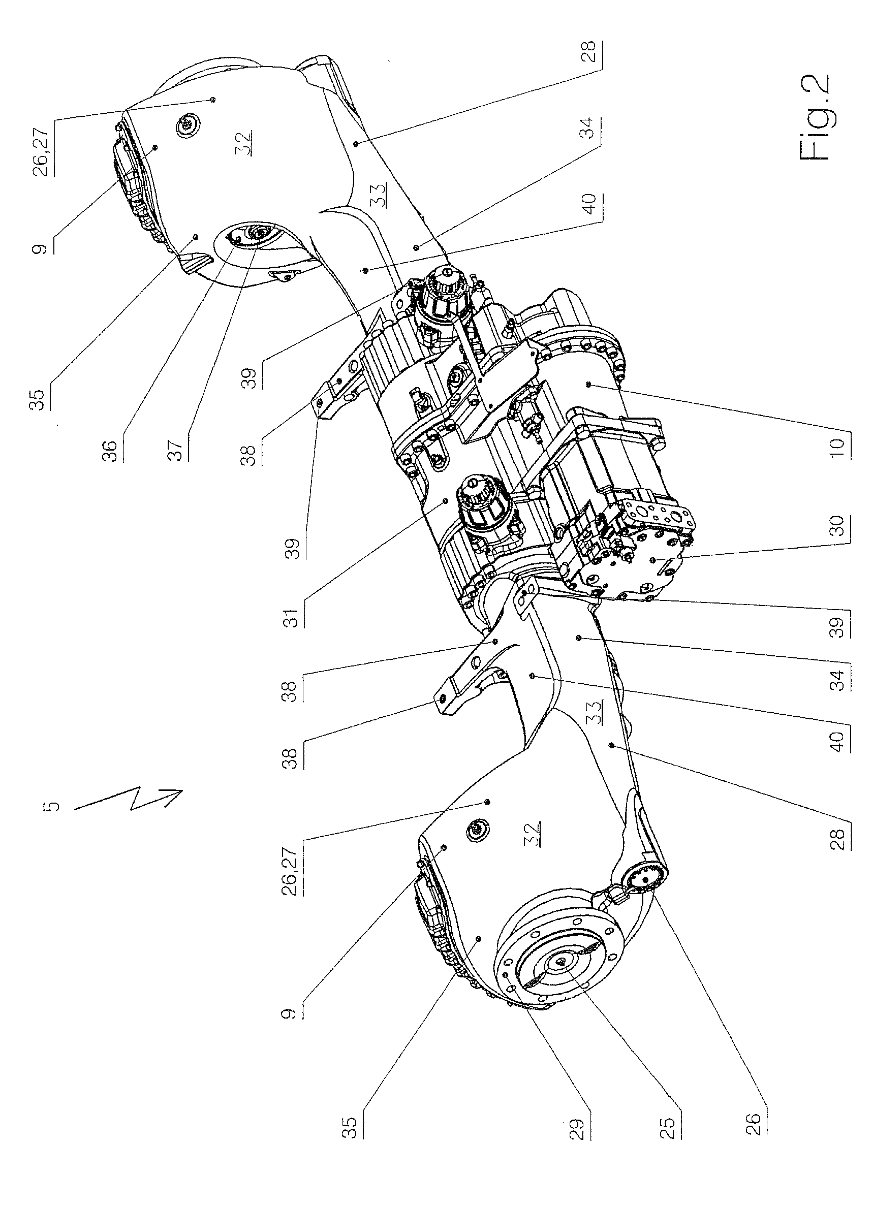
[0021]FIG. 1 is a schematic depiction of a self-propelled forage harvester 1, which serves to pick up and process crop material. Forage harvester 12 includes a ground drive, which is formed by a machine frame 4. Machine frame 4 is a carrier for individual components. The location of the components on machine frame 4 plays an essential role in terms of the efficiency of forage harvester 1. The components located underneath frame 4 are front axle 5 and rear axle 6, each of which includes wheels 7, 8. Drive wheels 7, axle carrier units 28 with wheel gears 9, and a transmission 10 are installed on front axle 5. Rear axle 6, which is preferably designed to be height-adjustable, is designed as a swing axle 6, and is resiliently supported relative to machine frame 4, carries steering wheels 8 and, along with drive wheels 7, supports machine frame 4 on ground 11. The upper components are located above machine frame 4, i.e., driver's cab 12 and a machine housing 13. Processing devices, e.g.,...


PUM


Abstract

The present invention relates to a self-propelled forage harvester (1) that is equipped with a front attachment (3) and includes a rigid axle (5), a transmission (10) and two wheel gears (9), which are installed upstream of the drive wheels (7) and are coupled with the transmission (10) in a driving manner, the drive axle (5) being composed of a center part (31) and axle carrier units (28) rigidly flange-connected on the right and left sides of the center part (31), each axle carrier unit (28) including wheel gears (9) that extend forward, in the direction toward the front attachment (3).

Description

CROSS-REFERENCE TO A RELATED APPLICATION[0001]The invention described and claimed hereinbelow is also described in German Patent Application DE 10 2007 036 292.9 filed on Jul. 31, 2007. This German Patent Application, subject matter of which is incorporated herein by reference, provides the basis for a claim of priority of invention under 35 U.S.C. 119(a)-(d).BACKGROUND OF THE INVENTION[0002]The present invention relates to a self-propelled forage harvester. Every self-propelled forage harvester is built on a ground drive, which is composed of a machine frame. The machine frame serves as a carrier for individual components. The location of the components on the machine frame plays an essential role in terms of the efficiency of the forage harvester. The components located underneath the frame are the front axle and the rear axle, each of which includes wheels. The drive wheels, wheel gears, and a transmission are installed on the front axle. The steering wheels are installed on the ...

Claims


Application Information

Patent Timeline
Patent Type & Authority Patents(United States)
IPC IPC(8): B60K17/16
CPCA01D67/00A01D43/081
Inventor ISFORT, HEINRICHGERSMANN, MANFREDENGENHORST, WERNER
Owner CLAAS SELBSTFAHRENDE ERNTEMASCHINEN GMBH
Why Eureka
Try Eureka