Hydraulic vehicle brake system having a service brake which can be actuated by muscle force and having a device for regulating the wheel slip

a technology of hydraulic vehicle brakes and brake pads, which is applied in the direction of brake systems, vehicle components, braking components, etc., can solve the problems of affecting the brakes of the wheel, increasing the cost of modular system development and maintenance, and adversely affecting production costs and the resultant structural volume, so as to reduce the number of individual parts and improve the functional properties. , the effect of saving resources

Inactive Publication Date: 2011-10-25
ROBERT BOSCH GMBH
View PDF9 Cites 3 Cited by
  • Summary
  • Abstract
  • Description
  • Claims
  • Application Information

AI Technical Summary

Benefits of technology

[0012]A hydraulic vehicle brake system according to the invention has the advantage over the prior art that it makes do with fewer different individual parts and is thus more economical. The individual parts used can be used both for anti-lock vehicle brake systems and for traction control or stability control programs. A vehicle brake system of the invention has improved functional properties during the regulation of the wheel slip, and because of the reduced number of individual parts, it makes more-compact dimensions of its hydraulic unit possible. These advantages are attained, among other ways, by the use of a self-aspirating pump for all the different kinds of vehicle brake systems, that is, including for purely anti-lock brake systems, in conjunction with hydraulic reservoirs that are each supplied with pressure fluid via an inlet and via an outlet separate from the inlet. The reservoirs used have a freely movable separator element, disposed between two end positions, for dividing a first storage chamber from a second storage chamber. Furthermore, this separator element is capable, in one of its end positions, of blocking off a pressure fluid-conducting connection from the inlet to the outlet of the reservoir. It functions without an additional spring element, and as a result, the volume of pressure fluid that can be stored in the storage chamber is increased, in comparison to a spring piston reservoir, while the dimensions are unchanged. Moreover, the reservoir has a pressure / volume characteristic curve with improved hysteresis, since the influence of the spring element on the hysteresis is eliminated. Further advantages or advantageous refinements of the invention will become apparent from the ensuing description.
[0013]A check valve of special embodiment is disposed in the outlet of the reservoir. This check valve prevents a return flow of pressure fluid to the storage chamber of the reservoir and, because of the additional sealing function of the separator element of the reservoir, it can also be embodied without a restoring spring. Besides the savings in terms of parts costs, the check valve thus is more compact and more economical, compared to known arrangements. Such a check valve is necessary only in vehicle brake systems with an electronic stability program or traction control, since in those cases a buildup of brake pressure can occur independently of the driver, and since for this pressure buildup, pressure fluid may under some circumstances have to be aspirated from the master cylinder by the pump. In that case, the check valve prevents pressure fluid coming from the master cylinder from flowing into the reservoir. Anti-lock vehicle brake systems make do without this check valve.

Problems solved by technology

A defective, leaky check valve, in conjunction with the sole supply conduit of the reservoir, would have the effect that the underpressure generated by the self-aspirating pump could affect the wheel brakes.
The driver could perceive this from a long pedal travel, which could be irritating with regard to the capability of the vehicle brake system to function.
Furthermore, the number of different components for vehicle brake systems with a variable functional scope increases the costs for development and maintenance of a modular system.
In addition, relatively many individual components have to be installed to make the known vehicle brake systems, which adversely affects production costs and the resultant structural volume.

Method used


Image

  • Hydraulic vehicle brake system having a service brake which can be actuated by muscle force and having a device for regulating the wheel slip
  • Hydraulic vehicle brake system having a service brake which can be actuated by muscle force and having a device for regulating the wheel slip
  • Hydraulic vehicle brake system having a service brake which can be actuated by muscle force and having a device for regulating the wheel slip

Examples


Embodiment Construction

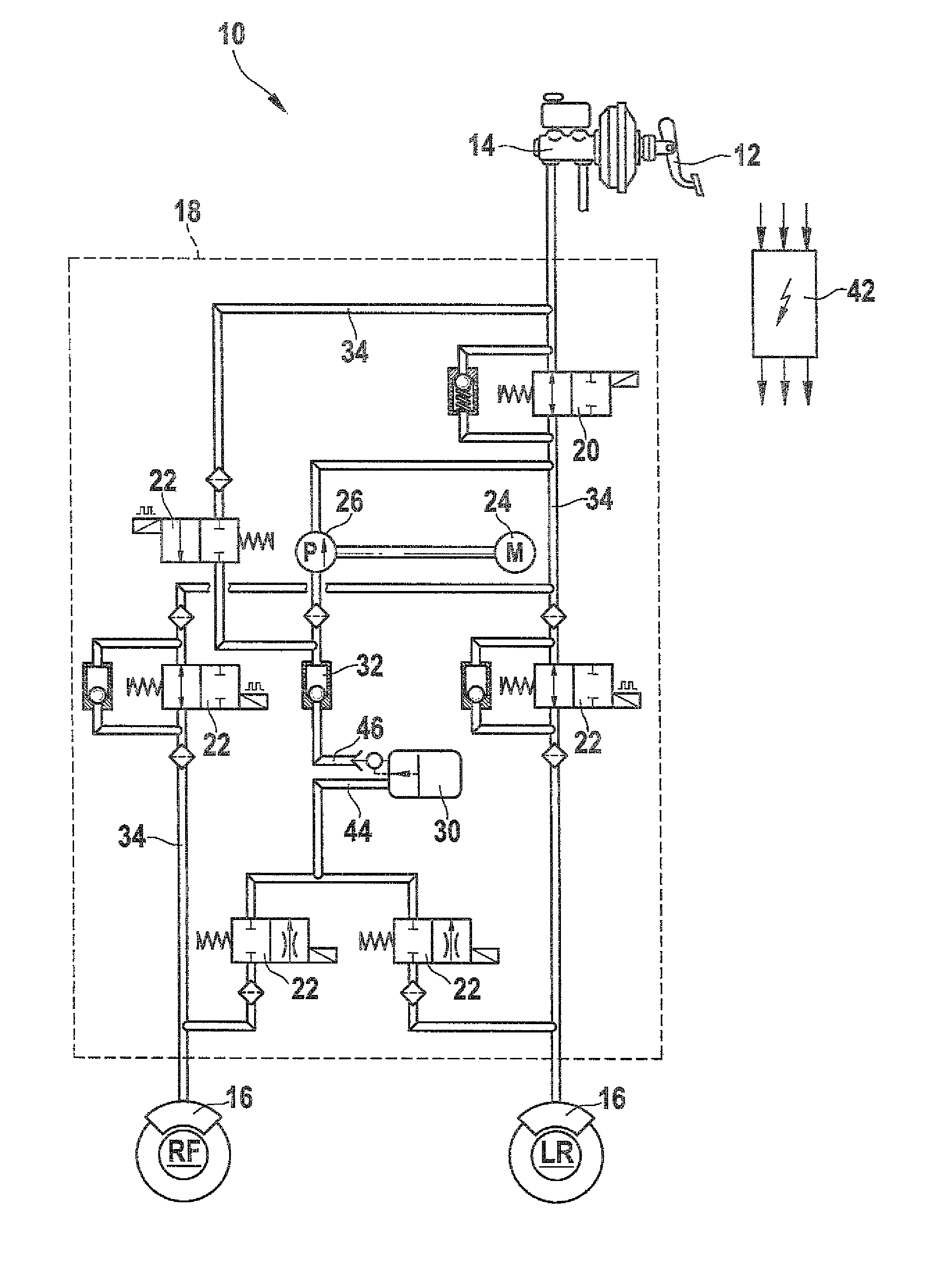
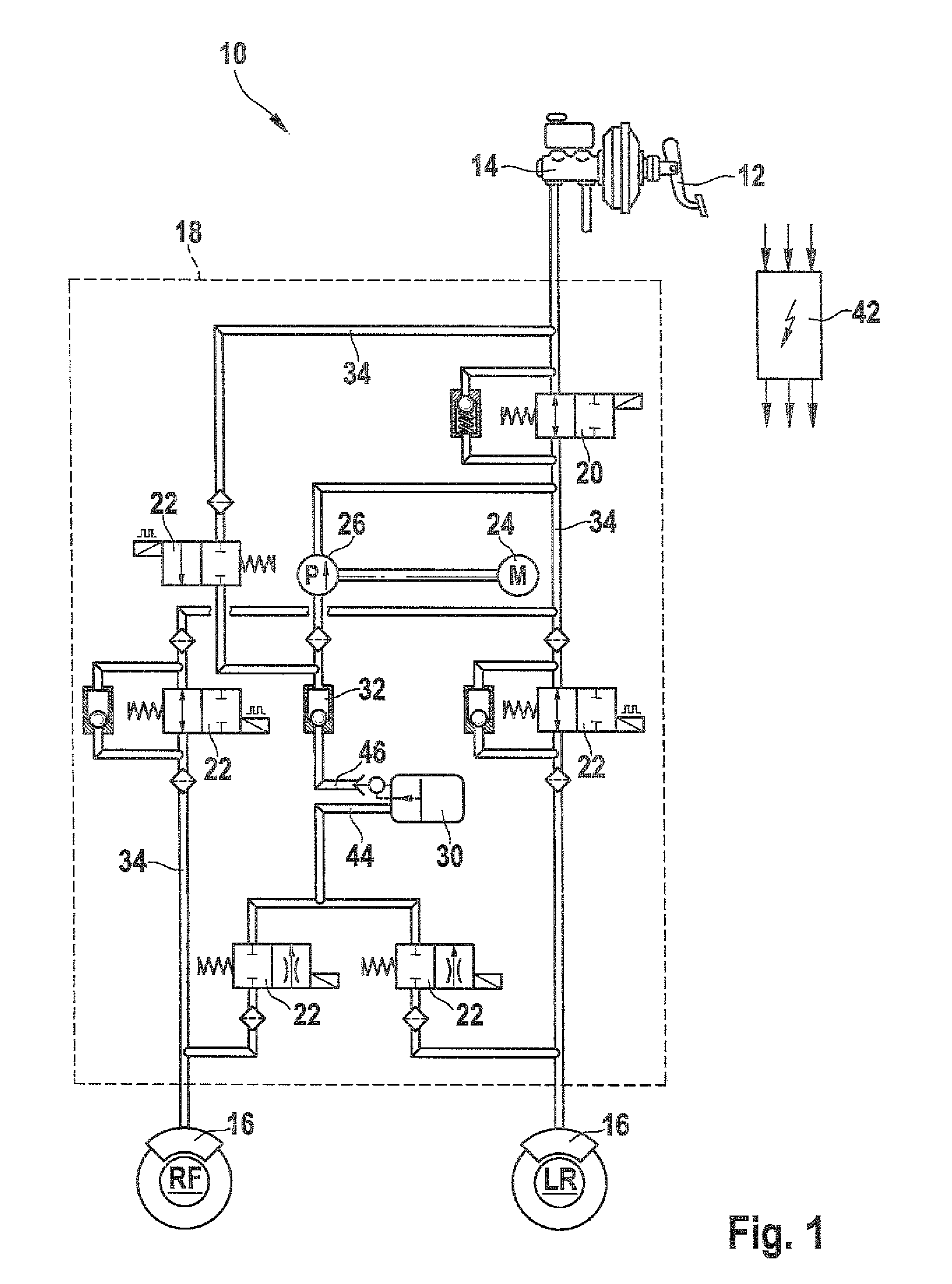
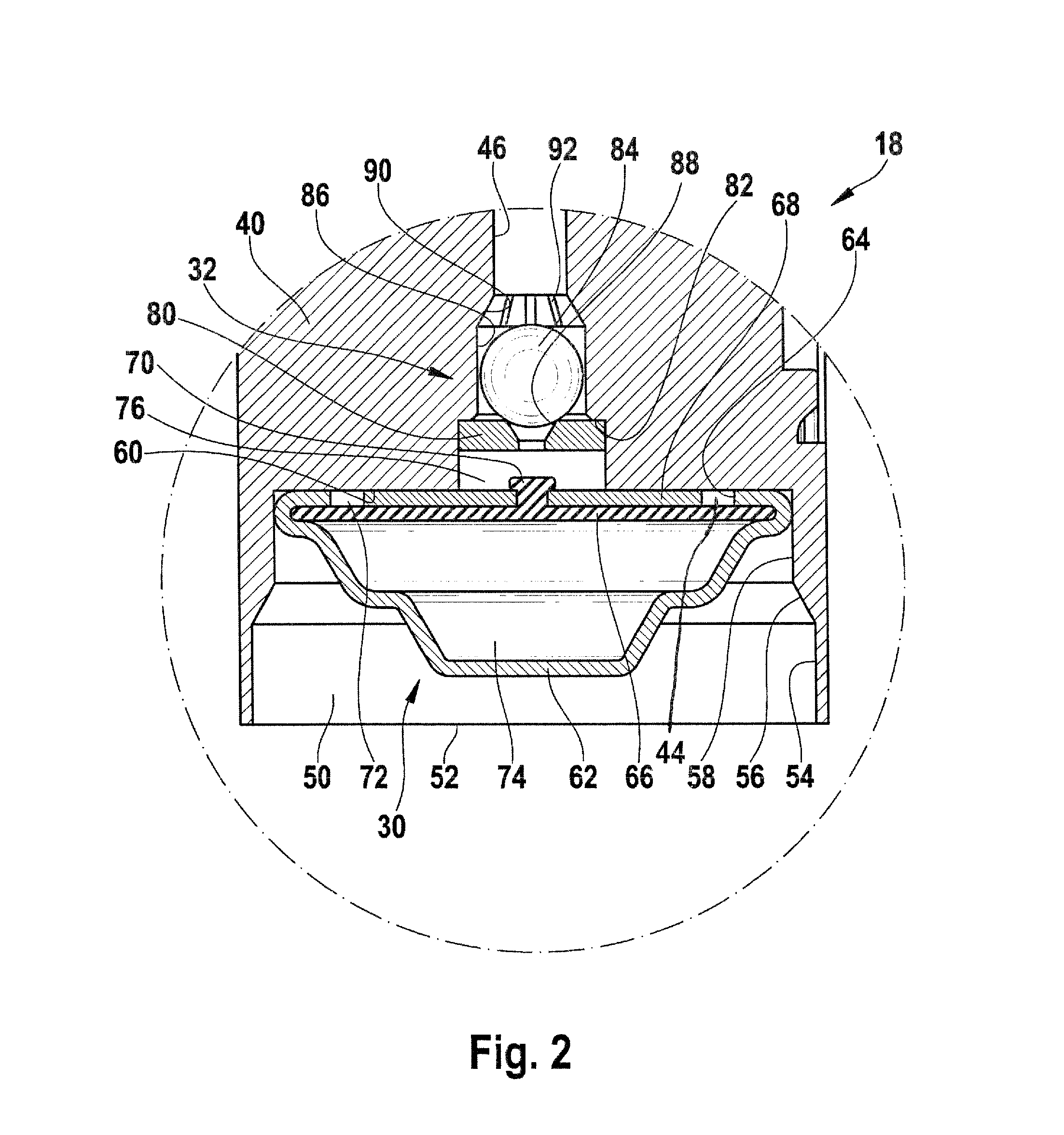
[0023]FIG. 1, in a schematic illustration, shows the circuit diagram of a hydraulic vehicle brake system 10 having a device for regulating wheel slip. A master cylinder 14 actuatable by a brake pedal 12 can be seen, along with two interconnected wheel brakes 16 in one brake circuit. A hydraulic unit 18 is disposed between the master cylinder 14 and the wheel brakes 16. This hydraulic unit 18 is shown in FIG. 1 by an outline shown in dashed lines. It includes various electromagnetically triggerable multi-way valves 20, 22, a pump 26 actuatable by a drive motor 24, a hydraulic reservoir 30 supplying the pump 26 with pressure fluid, and a check valve 32 located between the reservoir 30 and the pump 26. These hydraulic components mentioned are connected, on the basis of pressure fluid-carrying lines 34, to form a hydraulic circuit. These lines 34 are embodied as bores in a hydraulic block 40 (FIG. 2) of the hydraulic unit 18; in a later work operation, these bores are closed off from th...


PUM


Abstract

The invention relates to a hydraulic vehicle brake system having a service brake which can be actuated by muscle force and having a device for regulating the wheel slip. It is proposed in such a vehicle brake system to use suction pumps in connection with specially-designed accumulators. The accumulators have separating elements which in each case separate a first accumulator chamber from a second accumulator chamber. An inflow opens out into the first accumulator chamber, and an outflow, which is separate from the inflow, outlets out of the first accumulator chamber. The separating element is arranged so as to be freely movable between two end positions, and in one of its end positions, blocks a pressure medium connection of the inflow to the outflow.

Description

CROSS-REFERENCE TO RELATED APPLICATION[0001]This application is a 35 USC 371 application of PCT / EP 2007 / 054051 filed on Apr. 25, 2007.BACKGROUND OF THE INVENTION[0002]1. Field of the Invention[0003]The invention is based on a hydraulic vehicle brake system having a service brake that can be actuated by muscle force and having a device for regulating wheel slip.[0004]2. Description of the Prior Art[0005]Wheel-slip-regulated vehicle brake systems are understood hereinafter to mean anti-lock vehicle brake systems (ABS), vehicle brake systems with traction control (TC), or vehicle brake systems with an electronic stability program (ESP). Such vehicle brake systems have a hydraulic unit connected between a master cylinder, which is actuatable by the driver, and at least one wheel brake. This hydraulic unit is equipped with, among other elements, magnetically actuatable multi-way valves, pumps, a pump drive, and reservoirs that supply the pumps with pressure fluid. For actuating the pump ...

Claims


Application Information

Patent Timeline
Patent Type & Authority Patents(United States)
IPC IPC(8): B60T8/32
CPCB60T8/4275B60T8/4872F15B1/12
Inventor WEH, ANDREASTANDLER, JUERGEN
Owner ROBERT BOSCH GMBH
Why Eureka
Try Eureka