Brake control apparatus

a technology of control apparatus and brake, which is applied in the direction of braking system, vehicle position/course/altitude control, instruments, etc., can solve the problems of inability to obtain reliable judgment, low electric voltage supplied to the sensor, and inability to reliably output the output signal of the sensor, etc., to achieve the effect of not rapidly changing the operation force of the brak

Active Publication Date: 2011-10-25
TOYOTA JIDOSHA KK
View PDF18 Cites 9 Cited by
  • Summary
  • Abstract
  • Description
  • Claims
  • Application Information

AI Technical Summary

Benefits of technology

[0013]In the present brake control apparatus, even if the electric voltage supplied from the power source to the at least one wheel-speed sensor may be not higher than the reference value, the rapid change of the operation force of the at least one brake can be restrained. That is, the operation force of the at least one brake can be prevented from being rapidly increased or decreased, and accordingly noise that may cause one or more passengers to feel discomfort or uneasiness can be restrained. In addition, useless consumption of energy can be reduced or avoided.
[0016]In the present brake control apparatus, the hydraulic pressure of the wheel cylinder is not rapidly increased from the restricted, intermediate level of the hydraulic-pressure range, or rapidly decreased from a higher pressure to the restricted intermediate level. Therefore, in the case where a hydraulic-pressure regulating valve is employed to regulate or control the hydraulic pressure of the wheel cylinder, a large amount of brake liquid does not flow through the regulating valve, which leads to preventing the generation of large sounds caused by the flowing of the large amount of brake liquid. In particular, if the voltage supplied from the power source to the wheel-speed sensor just temporarily lowers below the reference value because of cranking of an engine of the vehicle, then noise may be easily heard after the cranking ends. However, in the present brake control apparatus, the generation of large sounds caused by the flowing of the large amount of brake liquid can be effectively prevented.
[0018]The limitation-canceling inhibiting portion may be any means that eventually inhibits the limitation canceling portion from canceling the limitation of the operation force, i.e., may be one that directly inhibits the limitation canceling portion from canceling the limitation, or one that indirectly inhibits the limitation canceling portion from canceling the limitation, e.g., one that inhibits the sensor ignoring portion from ignoring the wheel-speed sensor. In the present brake control apparatus, even if the voltage supplied from the power source to the wheel-speed sensor may temporarily lower below the reference value because of, e.g., the cranking of the engine, the limitation canceling portion is inhibited from canceling the limitation. Therefore, the rapid change of the operation force of the brake can be prevented, and accordingly the generation of noise and / or the useless consumption of energy can be avoided.
[0021]For example, in the case where the limitation canceling portion cancels the limitation of the operation force of the brake and consequently the operation force of the brake is increased, the gradient of increase of the operation force may be restrained by the gradient restraining portion. In this case, the operation force is more moderately increased as compared with the case where the gradient of increase of the operation force is not restrained at all. Therefore, the generation of noise can be effectively restrained. In addition, for example, if a time duration in which the wheel-speed sensor is ignored is considerably short, then the operation force of the brake may be changed from increasing to decreasing, in a state in which the operation force is considerably low yet. Thus, the operation force of the brake can be prevented from being uselessly increased, which leads to restraining the useless consumption of energy. Meanwhile, in the case where the gradient of decrease of the operation force is restrained by the gradient restraining portion, the generation of noise when the operation force is decreased can be effectively restrained.

Problems solved by technology

In this case, however, if the output signal of the wheel-speed sensor is not reliable, then a reliable judgment cannot be obtained.
For example, if an electric voltage of an electric-power source that supplies an electric voltage to the wheel-speed sensor excessively lowers, then the electric voltage supplied to the sensor also lowers, and accordingly the output signal of the sensor may not be reliable.
That is, although the vehicle is, in fact, in its running state, it may be erroneously judged that the vehicle is in its stopped state.
In this case, if the upper limit of the hydraulic pressure of the wheel cylinder is restricted, then a braking force may be insufficiently low.
However, in the above-described case, the hydraulic pressure of the wheel cylinder may be increased rapidly, and noise may be produced mainly from a hydraulic-pressure regulating valve (i.e., a pressure-increase valve).
In addition, in the case where the voltage of the power source lowers just temporarily because of cranking of an engine, the power-source voltage may increase again in a considerably short time.
In this case, the ignoring of the wheel-speed sensor is stopped soon, and the hydraulic pressure of the wheel cylinder is decreased rapidly, that is, noise may be produced from a hydraulic-pressure regulating valve (i.e., a pressure-decrease valve).
In the case where the wheel-speed sensor is ignored because of cranking of the engine, the noise produced from the pressure-increase valve cannot be easily heard because the noise is mixed with the sounds produced by the cranking; but the noise produced from the pressure-decrease valve may be easily heard because the cranking has already ended, and accordingly one or more passengers in the vehicle feel discomfort or uneasiness.
In addition, since the hydraulic pressure of the wheel cylinder is increased or decreased temporarily, a certain amount of energy is uselessly consumed.
In addition, the electric brake suffers from the problem that a certain amount of energy is uselessly consumed.

Method used


Image

  • Brake control apparatus
  • Brake control apparatus
  • Brake control apparatus

Examples


first embodiment

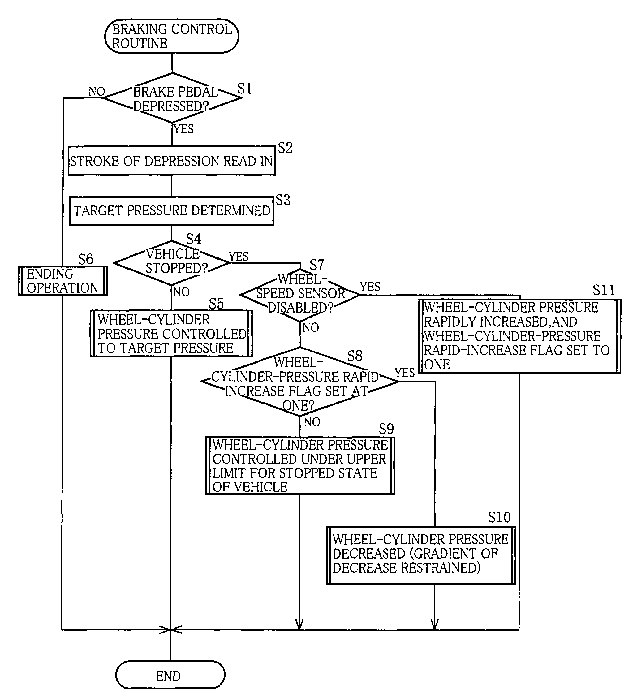
[0081]As is apparent from the foregoing description of the brake control apparatus, a portion of the brake ECU 150 that carries out Step S4 provides a vehicle-stopped-state detecting portion; a portion of the brake ECU 150 that carries out Step S9 provides a hydraulic-pressure limiting portion as a brake-operation-force limiting portion; and a portion of the brake ECU 150 that carries out Step S10 provides a gradient restraining portion. In addition, a portion of the brake ECU 150 that carries out Step S21 provides a detecting portion that detects that a power source is ineffective; a portion of the brake ECU 150 that carries out Step S23 cooperates with the detecting portion to provide a sensor-disablement judging portion as a sensor-ignoring judging portion; a portion of the brake ECU 150 that carries out Step S24 provides a sensor ignoring (disabling) portion; and a portion of the brake ECU 150 that carries out Step S1 provides a limitation canceling portion. Moreover, a portion ...

second embodiment

[0093]As is apparent from the foregoing description of the brake control apparatus, a portion of the brake ECU 150 that carries out Step S57 provides a cranking detecting portion; a portion of the brake ECU 150 that carries out Step S60 provides a hydraulic-pressure limiting portion as a brake-operation-force limiting portion; a portion of the brake ECU 150 that carries out Step S58 or S62 provides a detecting portion that detects that the power source is ineffective, or a sensor ignoring (disabling) portion; a portion of the brake ECU 150 that carries out Step S61 provides a limitation (or restriction) canceling portion; and a portion of the brake ECU 150 that carries out Step S63 or S64 provides a gradient restraining portion.

third embodiment

[0094]The rapid change of the operation force of the brake, caused by the cancellation of the limitation (or restriction) to the operation force, may be restrained by controlling the wheel-cylinder pressure under a second upper limit (i.e., a second restricted value) of the wheel-cylinder pressure for the ineffective state of the power source and is somewhat higher than the above-described, i.e., first upper limit (i.e., a first restricted value) of the wheel-cylinder pressure for the stopped state of the vehicle. This feature is embodied as a third embodiment shown in FIGS. 9 and 10.

[0095]The third embodiment differs from the second embodiment shown in FIGS. 7 and 8, only in that the third embodiment employs, in place of the braking control routine of FIG. 7, a braking control routine of FIG. 9 in which Steps S81 through S92 and S94 are identical with Steps S51 through S62 and S64, respectively, and only Step S93 replaces Step S63. At Step S93, the brake ECU 150 controls the wheel-...


PUM


Abstract

A brake control apparatus for controlling brakes of a vehicle having wheels, the apparatus including a stopped-state detecting portion which detects, based on a speed of at least one of the wheels detected by at least one wheel-speed sensor, a stopped state of the vehicle; an operation-force limiting portion which limits, based on a detection of the stopped state of the vehicle by the stopped-state detecting portion, an operation force of at least one of the brakes, such that an upper limit of the operation force is an intermediate level of an operation-force range used when the stopped state is not detected; a sensor ignoring portion which ignores, when an electric voltage supplied from a power source to the at least one wheel-speed sensor is not higher than a reference value, the at least one wheel-speed sensor; a limitation canceling portion which cancels, when the sensor ignoring portion ignores the at least one wheel-speed sensor, a limitation of the operation force by the operation-force limiting portion; and a rapid-change restraining portion which restrains a rapid change of the operation force caused by a cancellation of the limitation of the operation force by the limitation canceling portion.

Description

[0001]The present application is based on Japanese Patent Application No. 2006-218521 filed on Aug. 10, 2006, the contents of which are incorporated herein by reference.BACKGROUND OF THE INVENTION[0002]1. Field of the Invention[0003]The present invention relates to a brake control apparatus and particularly to the art of controlling an operation force of a brake of a vehicle in a state in which the vehicle is stopped.[0004]2. Discussion of Related Art[0005]For example, Japanese Patent Application Publication No. 2002-154415 or Japanese Patent No. 2,749,383 discloses a brake control apparatus wherein, when a vehicle is in its stopped state, an upper limit of an operation force of a brake is made lower than an upper limit of the operation force when the vehicle is running, i.e., in its running state. In the disclosed brake control apparatus, a hydraulic brake that operates upon supplying of a hydraulic pressure to a wheel cylinder thereof is controlled such that if it is judged, based...

Claims


Application Information

Patent Timeline
Patent Type & Authority Patents(United States)
IPC IPC(8): B60T8/60
CPCB60T7/042B60T8/4081B60T8/885B60T13/745B60T13/686B60T2270/416B60T2270/402B60T2270/413
Inventor YAMAMOTO, TAKAYUKIKOMAZAWA, MASAAKIHANAKI, YASUSHI
Owner TOYOTA JIDOSHA KK
Why Eureka
Try Eureka