Compressor casing for an exhaust gas turbocharger

a compression casing and turbocharger technology, applied in the direction of liquid fuel engines, instruments, fluid couplings, etc., can solve the problems of swept volume, increased engine speed, increased engine speed, etc., and achieves compact and inexpensive production, especially small

Inactive Publication Date: 2011-10-25
CONTINENTAL AUTOMOTIVE GMBH
View PDF20 Cites 8 Cited by
  • Summary
  • Abstract
  • Description
  • Claims
  • Application Information

AI Technical Summary

Benefits of technology

[0018]In an embodiment the sensor is configured on a leadframe as a micromodule with the sensor element and/or the signal processing electronics and/or a protection circuit and/or an interference suppression circuit. This embodiment is very economical, as the leadframe with the electronic components configured thereon can be injection-molded directly. In this case a separate sensor housing is dispensed with entirely, since the compressor casing also forms the sensor housing. If the compressor casing is formed from a plastics material, the micromodule also does not require separate electrical insulation because the electrical insulation of the sensor is also achieved through the plastics material of the compressor casing. In addition, according to this embodiment the sensor can be produced especially small, compact and inexpensive. The sensor in the form of a micromodule can also be used in other assemblies for measuring rotational speed—for example, in measuring the rota...

Problems solved by technology

However, an increase in swept volume leads in principle to heavier engines of larger dimensions, which are therefore more expensive.
The increase in engine speed entails considerable problems and disadvantages, especially in the case of relatively large internal combustion engines, and is limited for technical reasons.
Impermissible exceeding of the speed of the rotor would destroy the latter, which is equivalent to total loss of the turbocharger.
In particular modern, small turbochargers with significantly smaller turbine wheel and compressor wheel diameters, which have improved rotational acceleration behavior through a considerably lower...

Method used


Image

  • Compressor casing for an exhaust gas turbocharger
  • Compressor casing for an exhaust gas turbocharger
  • Compressor casing for an exhaust gas turbocharger

Examples


Embodiment Construction

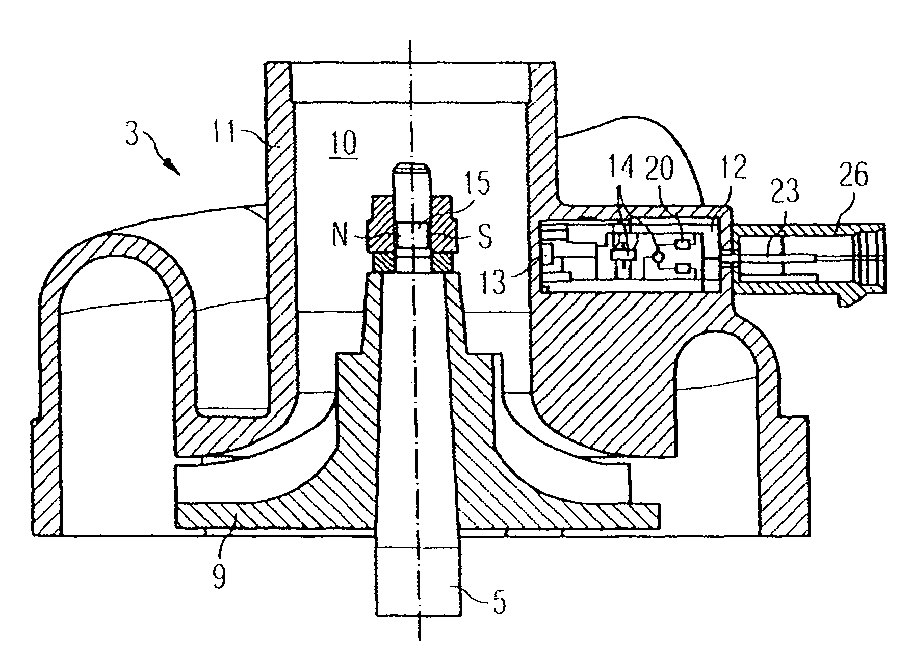
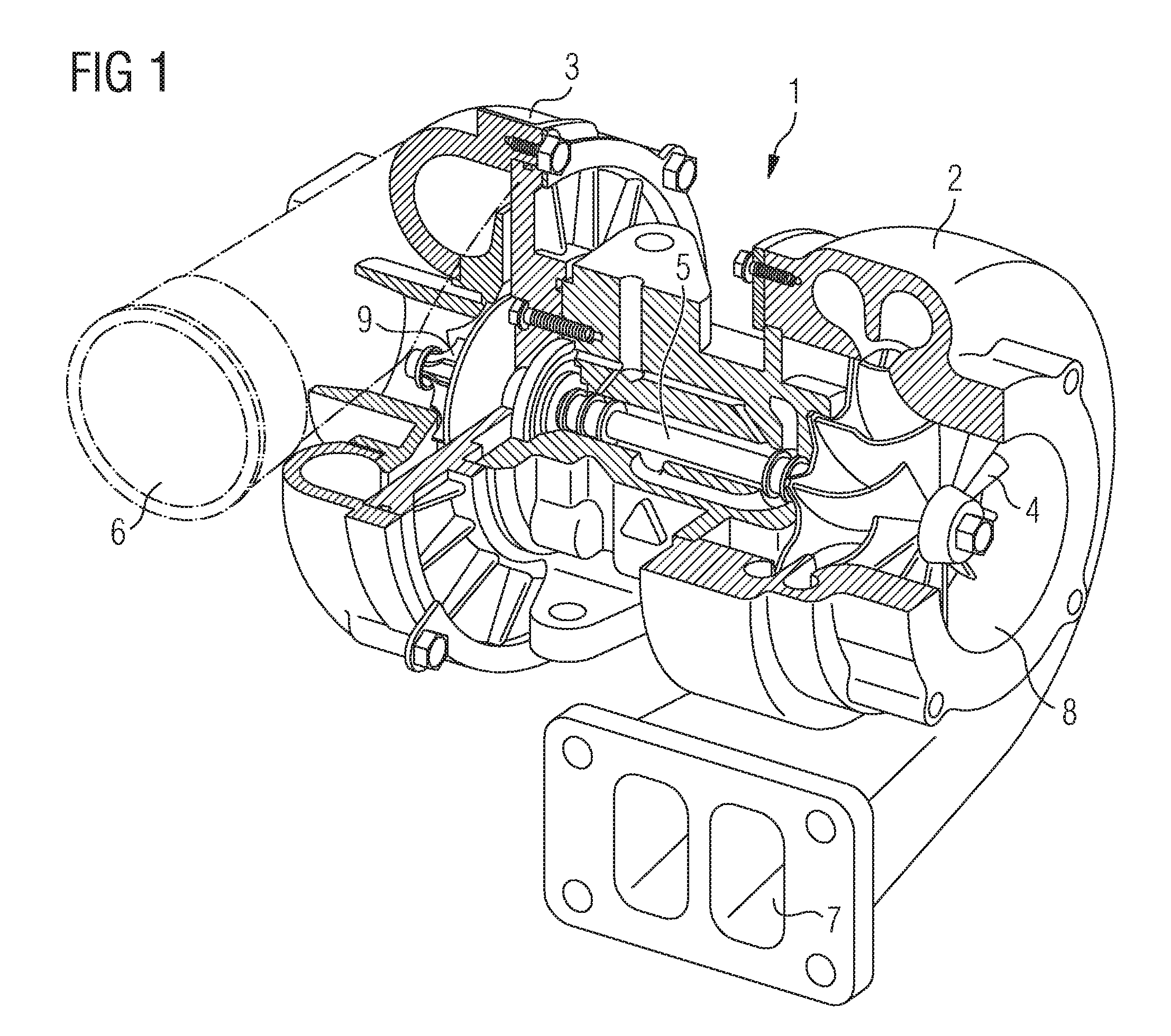
[0028]FIG. 1 shows an exhaust gas turbocharger 1 with a turbine 2 and a compressor 3. The compressor wheel 9 is mounted rotatably in the compressor 3 and is connected to the turboshaft 5. The turboshaft 5 is also mounted rotatably and is connected at its other end to the turbine wheel 4. Hot exhaust gas from an internal combustion engine (not shown here) is admitted to the turbine 2 via the turbine inlet 7, the turbine wheel 4 being set in rotation. The exhaust gas flow leaves the turbine 2 through the turbine outlet 8. The turbine wheel 4 is connected to the compressor wheel 9 via the turboshaft 5. The turbine 2 thus drives the compressor 3. Air is aspirated into the compressor 3 through the air intake 10 and supplied via the air outlet 6 to an internal combustion engine (not shown here).

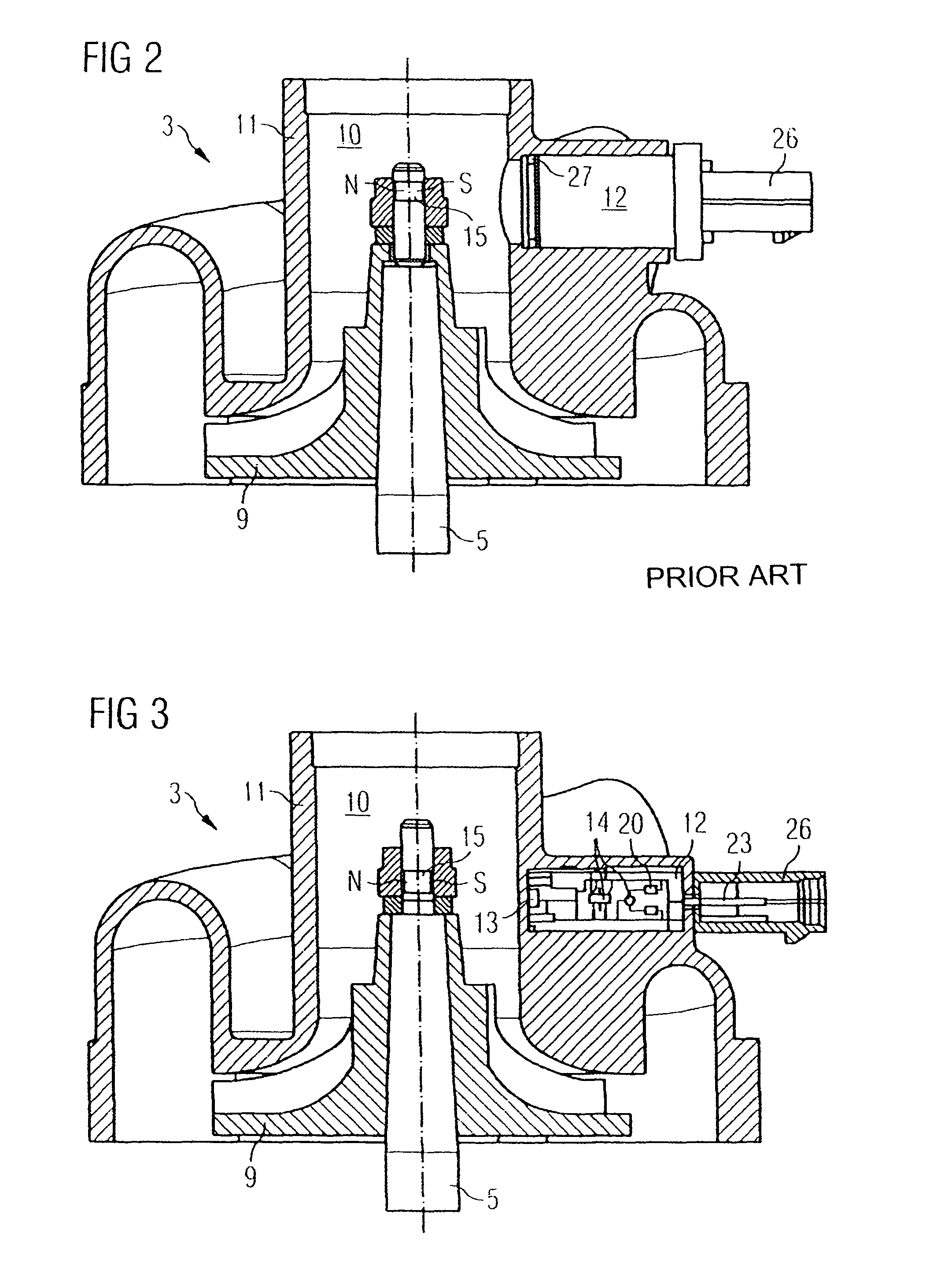
[0029]FIG. 2 shows the compressor 3 of an exhaust gas turbocharger 1 with a sensor 12 for measuring the rotational speed of the turboshaft 5 according to the prior art. The exhaust gas turbocharger...


PUM

PropertyMeasurementUnit
Speedaaaaaaaaaa

Abstract

A compressor casing for an exhaust gas turbocharger is disclosed. The exhaust gas turbocharger has a rotatable turboshaft, a compressor wheel mounted on the turboshaft, and a turbine wheel mounted on the turboshaft. The compressor casing includes a sensor for measuring a rotational speed of the turboshaft. The sensor is embedded in the compressor casing and forms an integral component of the compressor casing.

Description

CROSS-REFERENCE TO RELATED APPLICATIONS[0001]This is a U.S. national stage of International Application No. PCT / EP2007 / 050278, filed on 12 Jan. 2007. Priority is claimed on Germany Application No. 10 2006 003 599.2, filed on 25 Jan. 2006.BACKGROUND OF THE INVENTION[0002]1. Field of the Invention[0003]2. Description of the Related Art[0004]The power generated by an internal combustion engine depends on the air mass and the fuel quantity which can be made available to the engine for combustion. In order to increase the power of an internal combustion engine, the quantity of combustion air and fuel supplied must be increased. In the case of a naturally aspirated engine, this power increase is achieved by an increase in swept volume or by increasing the engine speed. However, an increase in swept volume leads in principle to heavier engines of larger dimensions, which are therefore more expensive. The increase in engine speed entails considerable problems and disadvantages, especially i...

Claims


Application Information

Patent Timeline
IPC IPC(8): F01B25/04
CPCF01D17/06F01D21/003F01D25/24F02B67/10F04D27/001F04D27/0261G01P1/026G01P3/487G01P3/488F04D29/4206Y10T29/4924F05D2220/40Y10T29/49243Y02B30/70F04D29/40
Inventor ANTE, JOHANNESGILCH, MARKUS
Owner CONTINENTAL AUTOMOTIVE GMBH
Why Eureka
Try Eureka