Electrochemical cell stacks

a technology of electrochemical cells and stacks, applied in the field of electrochemical apparatus, can solve the problems of stress being applied to the cells, and achieve the effect of preventing the application of stress between the electrochemical cells

Inactive Publication Date: 2011-10-25
NGK INSULATORS LTD
View PDF15 Cites 8 Cited by
  • Summary
  • Abstract
  • Description
  • Claims
  • Application Information

AI Technical Summary

Benefits of technology

[0004]For stacks (batteries) such as described in WO 2007 / 029860 A1, cells that include, in the inside thereof, a gas flow channel are attached to stationary members, which are then stacked. However, since the thus-constructed cells also serve as structural members, stresses tend to be applied onto the cells. In particular, in light of lower structural strength of the cells including, in the inside thereof, a gas flow channel other than the cells having no such gas flow channel, therefore provides a desirable structure in which the cells alone are not subjected to stress.
[0005]An object of the present invention is to stack a plurality of electrochemical cells without applying an excessive stress onto the electrochemical cells.
[0008]In the stacked structure of the cells described in WO 2007 / 029860 A1, since the electrochemical cells also serve as the structural members, a stress tends to be exerted on the cells themselves. On the other hand, since, in the present invention, the plurality of electrochemical cells are supported by the coupled gas feed and discharge members in the state where the electrochemical cells are spaced apart from each other, the stress is applied only to the gas feed and discharge members, with a result that application of the stress between the electrochemical cells can be prevented.

Problems solved by technology

However, since the thus-constructed cells also serve as structural members, stresses tend to be applied onto the cells.

Method used


Image

  • Electrochemical cell stacks
  • Electrochemical cell stacks
  • Electrochemical cell stacks

Examples


Embodiment Construction

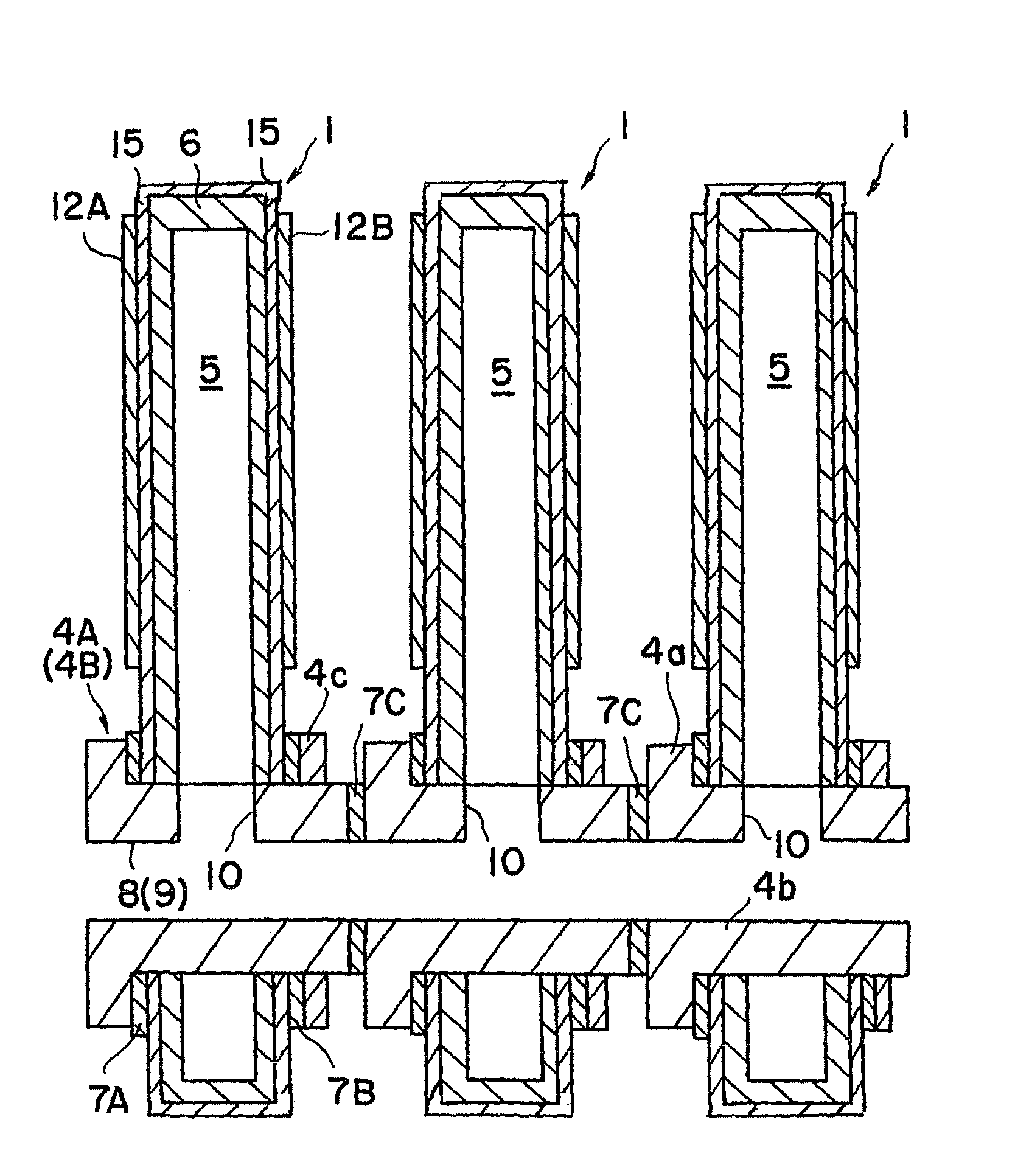
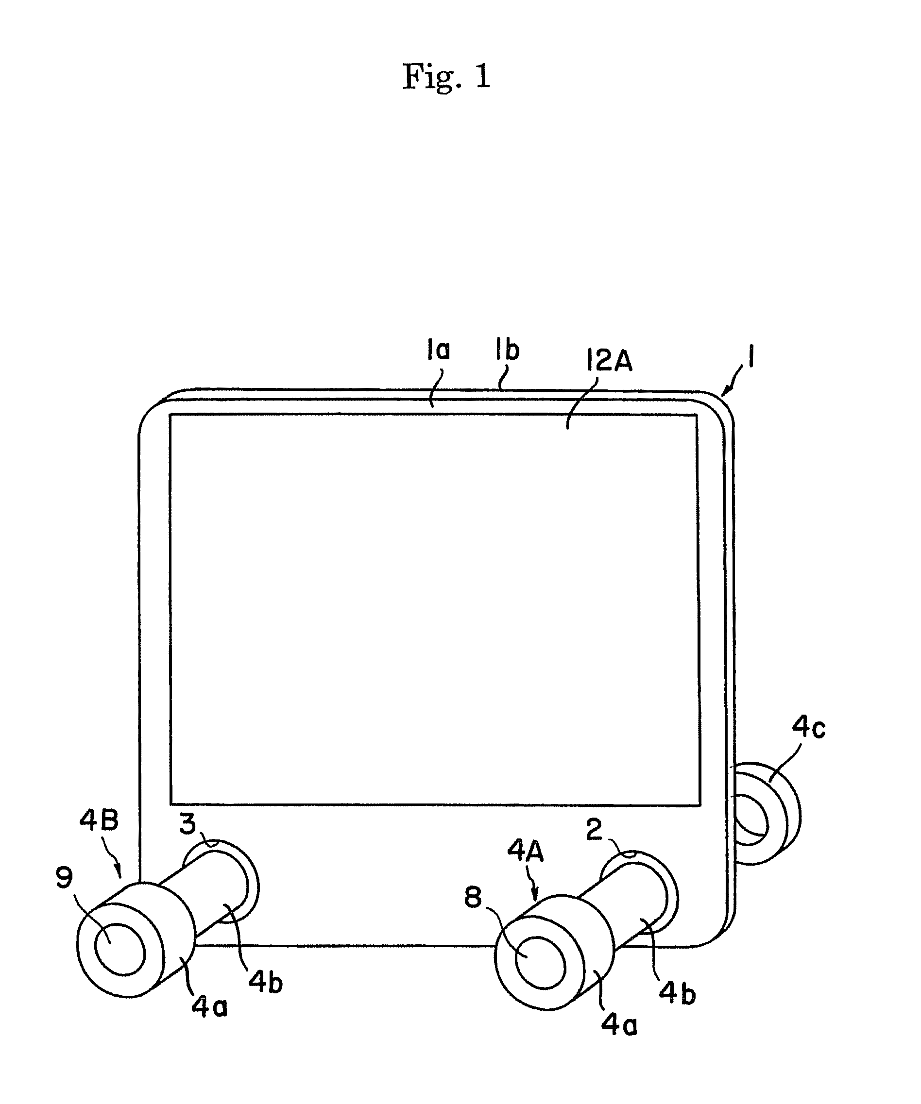
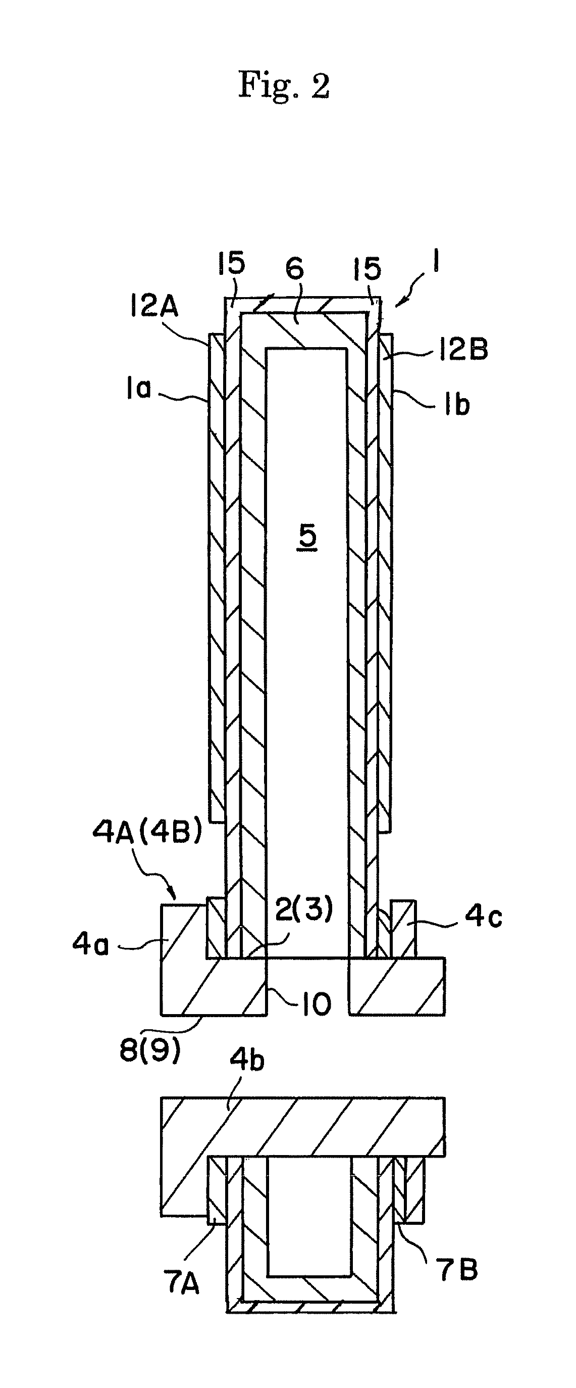
[0018]In the present invention, an electrochemical cell is preferably in the form of a plate. However, the electrochemical cell is not limited to a flat-shaped plate, and may be a curved plate or an arc-shaped plate. The electrochemical cell comprises a first electrode which comes into contact with a first gas, a solid electrolyte film, and a second electrode which comes into contact with a second gas.

[0019]Here, the first electrode and the second electrode are selected from an anode or a cathode. When one of the first and second electrodes is the anode, the other is the cathode. Similarly to this, the first gas and the second gas are selected from an oxidizing gas or a reducing gas.

[0020]The oxidizing gas is not particularly limited, and may be any gas as long as capable of supplying oxygen ions to the solid electrolyte film, including air, diluted air, oxygen, and diluted oxygen. As the reducing gas, H2, CO, CH4, and a mixed gas thereof are exemplified.

[0021]The electrochemical ce...


PUM

PropertyMeasurementUnit
voltageaaaaaaaaaa
temperaturesaaaaaaaaaa
surface roughnessaaaaaaaaaa

Abstract

An electrochemical apparatus having a plurality of ceramic electrochemical cells, a plurality of gas feed members and a plurality of gas discharge members. The electrochemical cell has a first electrode contacting with a first gas, a solid electrolyte layer and a second electrode contacting with a second gas. A gas flow channel for flowing the first gas therethrough, a first through hole and a second through hole are provided in the electrochemical cell. The gas feed member is inserted into the first through hole, the gas discharge member is inserted into the second through hole. The adjacent gas feed members are airtightly coupled to each other thereby forming a gas feed channel, and the adjacent gas discharge members are airtightly coupled to each other thereby forming a gas discharge channel.

Description

FIELD OF THE INVENTION[0001]The present invention relates to an electrochemical apparatus such as a solid oxide fuel cell.BACKGROUND OF THE INVENTION[0002]A plurality of cells must be laminated (stacked) in order to obtain a high power output since the voltage per fuel cell is approximately 1 V. For this reason, how the number of laminated cells can be increased to obtain the high power output in a reduced size becomes an issue that needs to be solved.[0003]In WO 2007 / 029860 A1, especially in FIG. 14, a fuel flow channel is formed, for example, inside a fuel electrode of a ceramic electrochemical cell, in which a solid electrolyte film and an air electrode film are formed on the fuel electrode. Then, after providing a gas feed port and a gas discharge port to a cell itself, a plurality of the cells are directly laminated to form a stack. In the course of constructing the stack, the gas feed port of each of the adjacent cells are arranged so as to continue to each other, thereby form...

Claims


Application Information

Patent Timeline
Patent Type & Authority Patents(United States)
IPC IPC(8): H01M2/38
CPCH01M8/2425H01M8/2485H01M8/04089Y02E60/525H01M2008/1293Y02E60/50H01M8/2483H01M8/2432
Inventor OKAMOTO, TAKURYU, TAKASHI
Owner NGK INSULATORS LTD
Why Eureka
Try Eureka