Control system for a marine vessel hydraulic steering cylinder

a control system and hydraulic steering technology, applied in underwater vessels, non-deflectable wheel steering, electric devices, etc., can solve the problems of affecting the mass production of valves, slow piston actuation in one direction,

Active Publication Date: 2011-10-25
BRUNSWICK CORPORATION
View PDF45 Cites 49 Cited by
  • Summary
  • Abstract
  • Description
  • Claims
  • Application Information

AI Technical Summary

Benefits of technology

[0047]A hydraulic cylinder control system made in accordance with a preferred embodiment of the present invention comprises a piston disposed within the hydraulic cylinder to define a first cavity on a first side of the piston and a second cavity on a second side of the piston, a pump configured to provide a flow of pressurized hydraulic fluid, a first valve connected in fluid communication between the pump and the hydraulic cylinder, a second valve connected in fluid communication with the hydraulic cylinder. The first valve is configured to selectively conduct the hydraulic fluid to one of the first and second cavities which selected as a function of a first signal received by the first valve. The second valve is configured to selectively conduct the hydraulic fluid from one of the first and second cavities which is selected as a function of a second signal received by the second valve.
[0048]In a preferred embodiment of the present invention, it further comprises a microprocessor connected in signal communication with the first and second valves and configured to provide the first and second signals to control the flow of the hydraulic fluid to and from the hydraulic cylinder. A preferred embodiment of the present invention can further comprise a steering device which is manually movable to control the movement of the marine vessel. The microprocessor is connected in signal communication with the steering device to receive a steering signal. The microprocessor determines the first and second signals as a function of the steering signal. The steering device can comprise a steering wheel and a sensor which is configured to provide the steering signal which is representative of the magnitude of rotation of the steering wheel.
[0049]In a preferred embodiment of the present invention, the hydraulic cylinder is a steering cylinder of a marine vessel. The first and second valves can be proportional valves. The second valve is configured to selectively conduct the hydraulic fluid from one of the first and second cavities to a reservoir for recirculation to the pump. The piston, which is disposed within the hydraulic cylinder housing, has a first surface facing the first cavity and a second surface facing the second cavity. The first surface has a larger area than the second surface. The first valve can be configured to control the rate of flow of hydraulic fluid from the pump to the hydraulic cylinder and to determine to which of the first and second cavities the flow of hydraulic fluid is directed. The second valve can be configured to control the rate of flow of hydraulic fluid from the hydraulic cylinder and to determine from which of the first and second cavities the flow of hydraulic fluid is drained.

Problems solved by technology

Reducing a valve with a quick response time within acceptable packaging constraints and with a structure that allows the valve to be mass produced with consistent performance between valves is problematic.
When a hydraulic cylinder and piston are used to actuate a steering device, there is an inherent problem that exists because of the presence of a single steering rod attached to one side of the piston.
However, in hydraulic cylinder devices that have one piston rod attached to one side of the piston, the actuation of the piston in one direction will naturally be at a slower rate than the retraction of the piston in the other direction.
This situation exacerbates the problem of maintaining very accurate positioning of a steering cylinder piston.

Method used


Image

  • Control system for a marine vessel hydraulic steering cylinder
  • Control system for a marine vessel hydraulic steering cylinder
  • Control system for a marine vessel hydraulic steering cylinder

Examples


Embodiment Construction

[0055]Throughout the description of the preferred embodiment of the present invention, like components will be identified by like reference numerals.

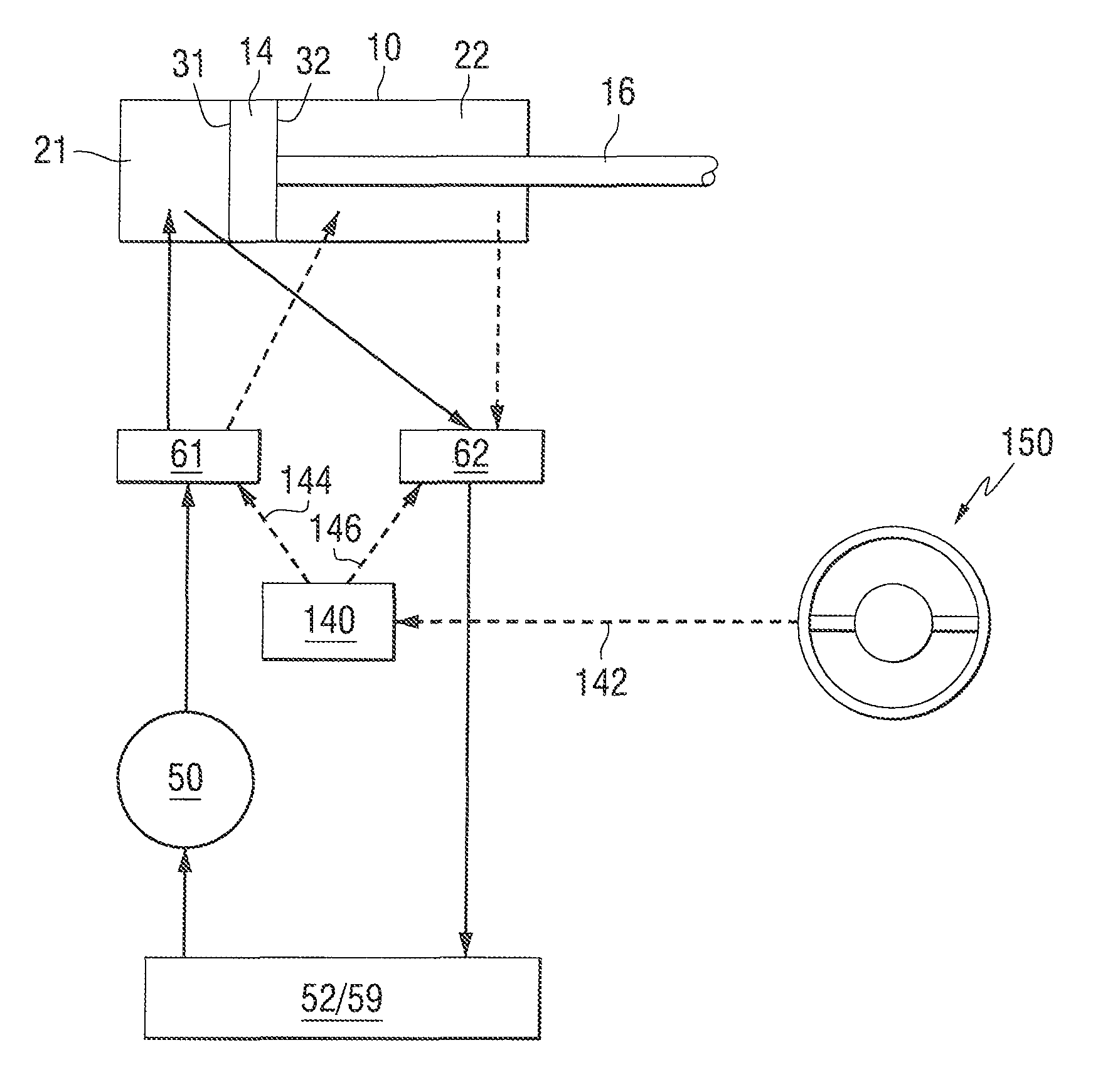
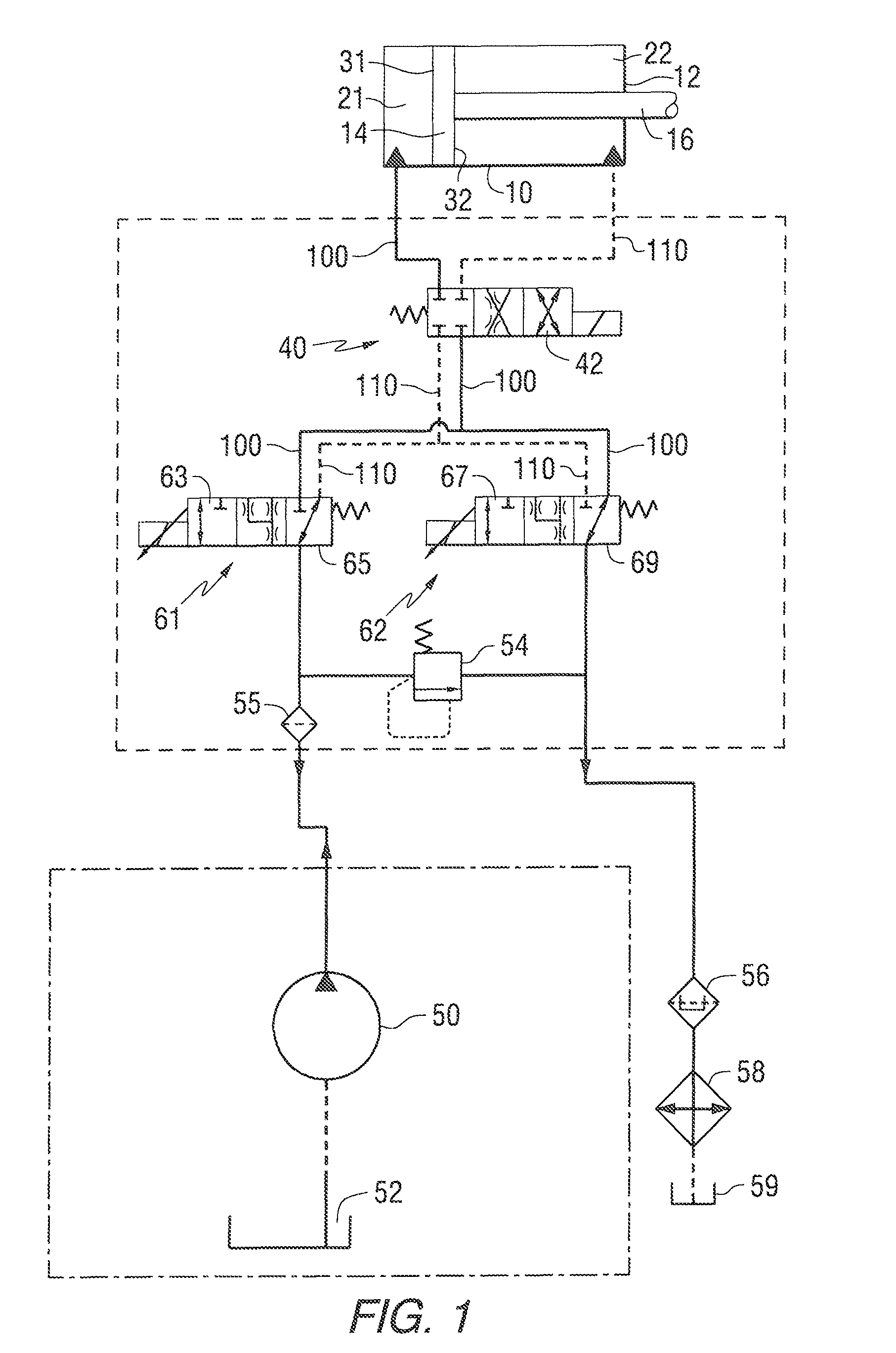
[0056]FIG. 1 is a schematic diagram of a hydraulic cylinder control system made in accordance with a preferred embodiment of the present invention. A steering cylinder 10 comprises a cylindrical housing 12 that has a piston 14 disposed therein. The piston 14 defines a first cavity 21 on a first side of the piston and a second cavity 22 on a second side of the piston. The piston 14 has a first surface 31 and a second surface 32. Because of the attachment of a piston rod 16 to the second surface 32, the effective area on which hydraulic fluid in the second cavity 22 can act is less than the effective area of the first surface 31. When hydraulic fluid is conducted into the first cavity 21, the piston rod 16 is actuated by movement toward the right inFIG. 1. Conversely, when pressurized hydraulic fluid is introduced into the second cavity 2...


PUM


Abstract

A control system for a hydraulic steering cylinder utilizes a supply valve and a drain valve. The supply valve is configured to supply pressurized hydraulic fluid from a pump to either of two cavities defined by the position of a piston within the hydraulic cylinder. A drain valve is configured to control the flow of hydraulic fluid away from the cavities within the hydraulic cylinder. The supply valve and the drain valve are both proportional valves in a preferred embodiment of the present invention in order to allow accurate and controlled movement of a steering device in response to movement of a steering wheel of a marine vessel.

Description

CROSS REFERENCE TO RELATED APPLICATIONS[0001]The present application is related to patent application Ser. No. 12 / 185,190 which was filed on the same date as the present application.BACKGROUND OF THE INVENTION[0002]1. Field of the Invention[0003]The present invention is generally related to a hydraulic steering cylinder control system and, more particularly, to a control system which uses two 3-way valves to control the rate of flow of hydraulic fluid to and from two sides of a piston and also selects the appropriate side of the piston that is supplied with pressurized oil and the side of the piston from which oil is drained in order to facilitate accurate and smooth movement of the piston within its hydraulic cylinder casing.[0004]2. Description of the Related Art[0005]Many types of hydraulic cylinder control systems are known to those skilled in the art. In addition, hydraulic cylinders used to actuate steering movements of vehicles are known to those skilled in the art. Some stee...

Claims


Application Information

Patent Timeline
Patent Type & Authority Patents(United States)
IPC IPC(8): F16D31/02G06F19/00
CPCB63H25/30F15B11/08F15B2211/20538F15B2211/3057F15B2211/3127F15B2211/3144F15B2211/327F15B2211/40515F15B2211/41536F15B2211/615F15B2211/62F15B2211/7053
Inventor BARTA, JASON C.FOLSOM, GREGORY C.
Owner BRUNSWICK CORPORATION
Why Eureka
Try Eureka