Eureka AIR delivers breakthrough ideas for toughest innovation challenges, trusted by R&D personnel around the world.

Channeled masonry flashing

Active Publication Date: 2011-11-01
HOHMANN & BARNARD INC
View PDF51 Cites 26 Cited by
  • Summary
  • Abstract
  • Description
  • Claims
  • Application Information

AI Technical Summary

Benefits of technology

[0028]In general terms the channeled masonry flashing of this invention provides a device combining the functions of draining water from a cavity wall, permitting the entry of air thereinto, and collecting mortar and construction debris in a manner that prevents the blockage of the drain. This is accomplished utilizing a flexible flashing membrane with channels in the top surface that are covered by a protective member. When a pressure-activated adhesive is added to the bottom surface together with a release sheet thereover, a peel-and-stick assemblage is formed. This facilitates a labor-saving application of the multi-functional device.
[0034]It is another object of the present invention to provide in a masonry flashing for cavity wall construction, combining clear hot melt adhesive and flashing membrane in a device free of bituminous or asphaltic coatings, which flashing resists drooling, tearing and puncturing.
[0035]It is yet another object of the present invention to provide a labor-saving masonry flashing which utilizes peel-and-stick components that are easy and economical to install in cavity wall constructs having a masonry block or drywall inner wythe and a brick or veneer outer wythe.
[0036]It is still yet another object of the present invention to provide a masonry flashing which has a built-in mortar protective member and drip edge and thus does not require the installation of separate flashing accessories such as mortar guards and weep hole fittings.
[0038]It is another feature of the present invention that the flashing membrane hereof is highly, ultraviolet resistant and the adhesive layer of the flashing enhances tear and puncture resistance of the overall structure and meets industry flammability standards.
[0039]It is yet another feature of the present invention that when the overall strength of the flashing is enhanced by a hot melt adhesive doped with fibrous reinforcement, the adhesive formulation is adjustable to maintain the tackiness required for bonding of the flashing with the inner wythe.

Problems solved by technology

Where excessive levels of water or water vapor are present in the cavity, the deterioration of building materials is hastened.
At that time the technology of pressure-sensitive hot melt adhesives needed for peel-and-stick applications was insufficiently developed.
Some critics indicated that the tackiness of the non-asphaltic products was insufficient for the rough masonry block surfaces.
Because of the presence of plasticizers, others were apprehensive about the available hot melt adhesives meeting the requisite fire retardancy standards.
However, these filled pressure-sensitive products had disadvantages, such as application problems, phase separation, toxicity, and reduced adhesion upon activation.
Here, in situ construction is both labor intensive and requires special equipment for installation.

Method used


Image

  • Channeled masonry flashing
  • Channeled masonry flashing
  • Channeled masonry flashing

Examples


first embodiment

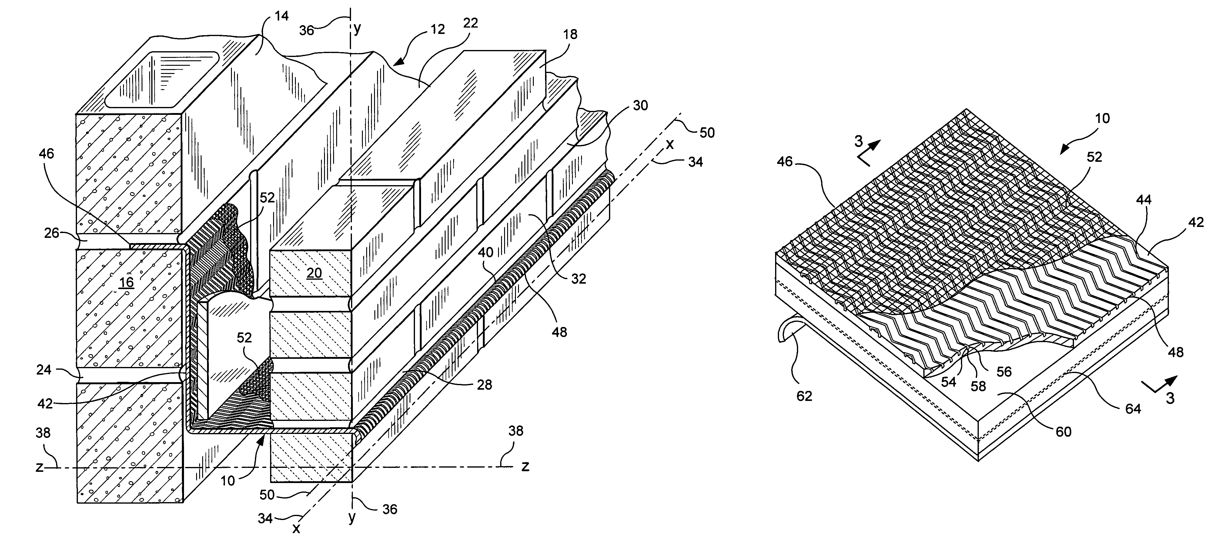
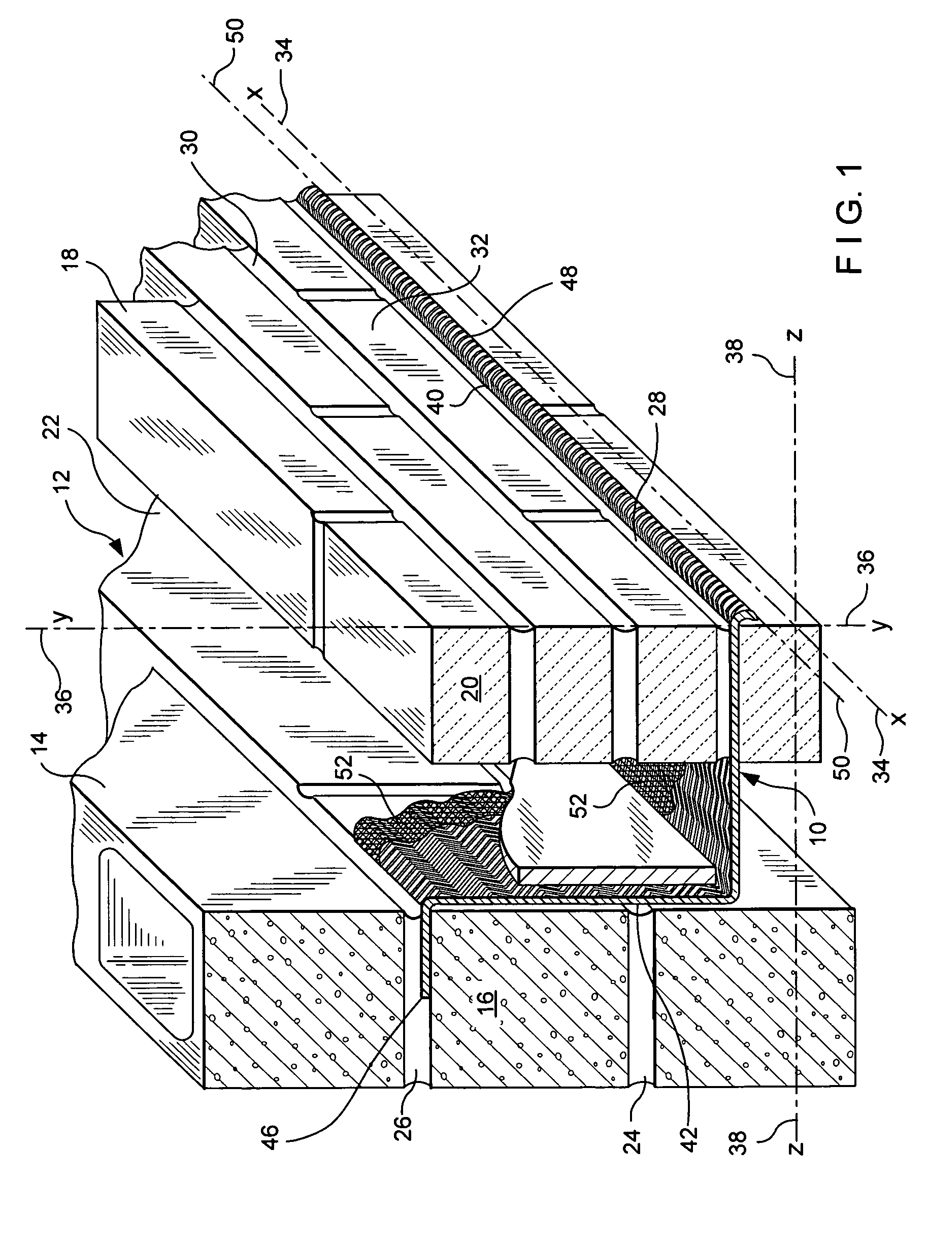
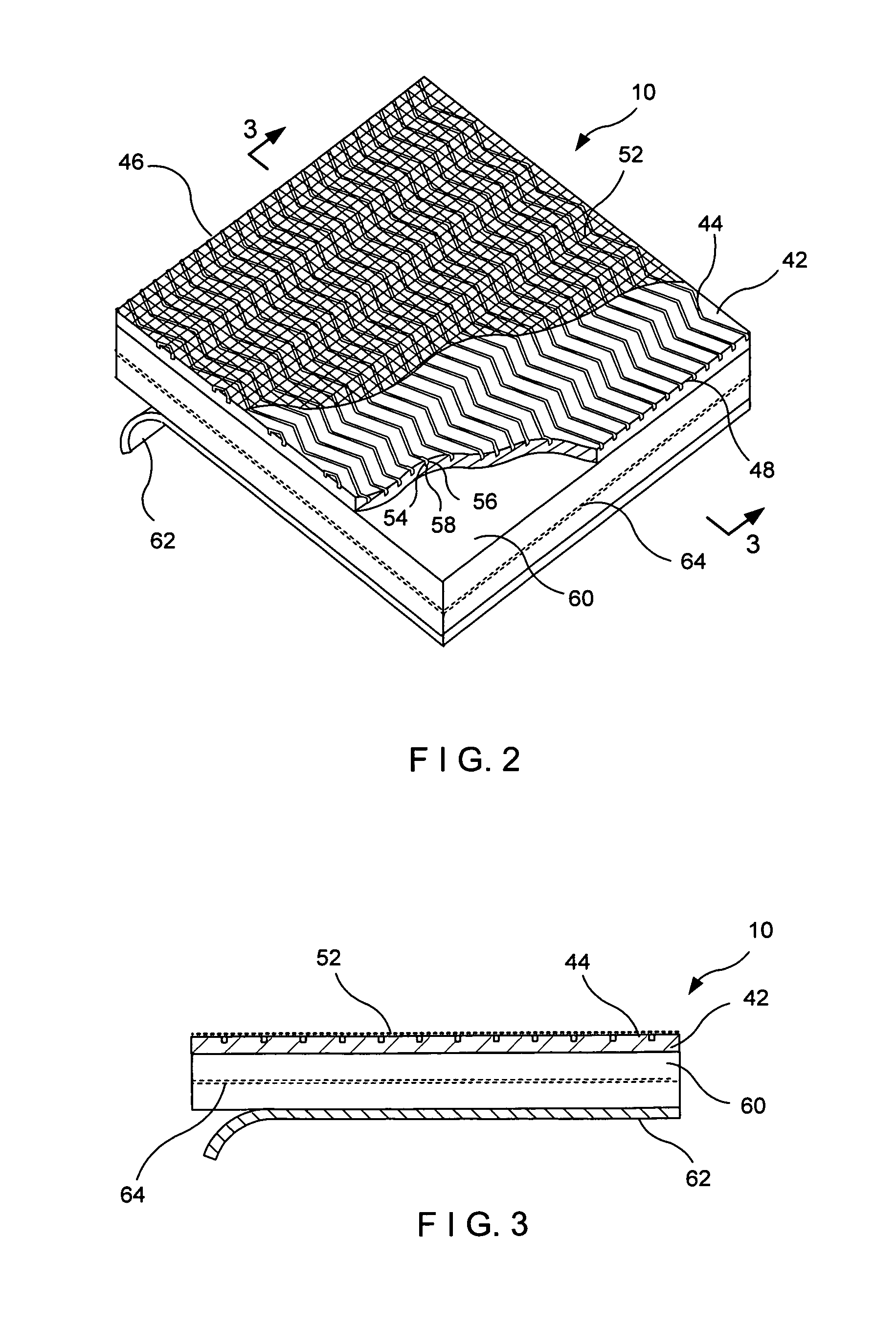
[0058]Referring how to FIGS. 1 through 3, this invention in which a channeled flashing assembly or masonry flashing structure referred to generally by the reference designator 10 is shown. In this embodiment, a cavity wall structure 12 is shown having an inner wythe 14 of masonry blocks 16 and an outer wythe 18 of facing brick 20. Between the inner wythe 14 and the outer wythe 18, a cavity 22 is formed. Successive bed joints 24 and 26 are formed between courses of blocks 16 and the joints are substantially planar and horizontally disposed. Also, successive bed joints 28 and 30 are formed between courses of bricks 20 and the joints are substantially planar and horizontally disposed. For the through-wall-mounted flashing installation of this embodiment the flashing 10 is shown extending into bed joint 26 of the inner wythe 14 and through bed joint 28 of the outer wythe 18.

[0059]For purposes of this discussion, the exterior surface 32 of the outer wythe 18 contains a horizontal line or...

second embodiment

[0080]The adhesive layer 160 of the second embodiment is an admixture of a hot melt adhesive (adapted as described above for sufficient tack) and a butylated adhesive. The latter is present in the total mixture in the range of 5 to 40 percent. In the present case, a 75 percent hot melt adhesive and a 25 percent butylated adhesive mixture provides a non-drool adhesive layer 148 which, upon curing, has a melting point of 225 degrees F. This aspect, when the melting point is above 200 degrees F., satisfies the stability requirement.

[0081]Referring now to FIGS. 7 through 9, the third embodiment of this invention in which a surface-mounted peel-and-stick channeled masonry flashing referred to generally by the reference designator 210, is shown. In this embodiment, similar parts to those of the first embodiment are referred to by reference designators 200 units higher than a similar part in the first embodiment. Thus, for example, the adhesive layer 60 in the first embodiment has an analo...


PUM

PropertyMeasurementUnit
Temperatureaaaaaaaaaa
Fractionaaaaaaaaaa
Percent by massaaaaaaaaaa

Abstract

A masonry flashing for use in a cavity wall is disclosed. The flashing has channels for draining water from the cavity while permitting entry of air into the cavity. The top surface of the flashing is covered by a protective member. The protective member is a scrim or, in the extruded form, an overarching portion of the flashing material. The protective member prevents the clogging of channels from mortar droppings and other construction debris. The flashing is shown with a drip edge is formed by extending the flashing beyond the external surface of the outer wythe and, with the edge being foil lined, manually forming the drip edge. A peel-and-stick embodiment described herein utilizes clear, nondrooling adhesives. Flashing accessories, namely, an end dam, an inside corner and an outside corner are also described.

Description

BACKGROUND OF THE INVENTION[0001]1. Field of the Invention[0002]This invention relates to an improved flashing system for cavity wall structures. More specifically the invention relates to channeled flashings having protected channels, which channels are protected from being clogged by mortar and construction debris. The flashings are designed for mounting with an open end of the channel in communication with the exterior of the cavity wall and the protected channel in the cavity to enable the channel to operate as a conduit between the cavity and the exterior.[0003]2. Description of the Prior Art[0004]In the past, investigations relating to cavity wall flashing systems for brick veneer masonry construction have been conducted. While strides have been made in flashing-related technologies, including metal foils, polymeric and elastomeric materials and hot melt adhesives, there still remain several areas where continued development is ongoing.[0005]The inventors' patents and their as...

Claims


Application Information

Patent Timeline
IPC IPC(8): E02D19/00
CPCE02D31/02E04B1/7046Y10T428/2826Y10T428/14Y10T442/164
Inventor HOHMANN, JR., RONALD P.
Owner HOHMANN & BARNARD INC
Why Eureka
Eureka Blog
Learn More