Tile gap seal assembly and method

a sealing assembly and tile technology, applied in the field of thermal protection systems, can solve the problems of affecting the overall utility of the seal, the difficulty of repairing and/or replacing the seal assembly or the tile, and the hardening compound applied over the filler bar that complicates the removal, repair and/or replacement of the til

Active Publication Date: 2011-11-01
THE BOEING CO
View PDF33 Cites 16 Cited by
  • Summary
  • Abstract
  • Description
  • Claims
  • Application Information

AI Technical Summary

Benefits of technology

[0014]The second bulb portion in combination with the spacer rope may be placed in sealing engagement with the tile gap to form a second seal that is redundant to the first seal for enhanced thermal protection of the substructure at the base of the tile gap. In this regard, the tile gap may be at least partially bounded by a substructure surface of the substructure. Furthermore, the seal assembly may be configured to be mounted within the tile gap in spaced relation to the substructure surface in order to form an inner gap between the seal assembly and the substructure. In this manner, the combination of the first and second seals and the inner gap advantageously provide thermal protection to the substructure such as against hot convective flow passing along the tile exterior surface (i.e., outer mold line). The first and second bulb portions, web and spacer rope are preferably fabricated of materials having low thermal conductivity to minimize heat transfer to the substructure.
[0016]Advantageously, the seal assembly as disclosed herein eliminates the need for structural fastening or bonding of the seal assembly to the substructure and / or to the tiles. The seal assembly may be installed within the tile gap in a simple operation by inserting the seal assembly into the tile gap in a folded configuration. Field removal of the seal assembly may be easily effectuated in order to repair a damaged seal assembly or for inspection, maintenance or replacement of tiles and / or substructure.
[0018]The web may be formed of material that is flexible, yet resiliently resistant to bending or wrapping around the spacer rope such that the combination of the web and spacer rope provides a biasing force for pushing or biasing the second bulb portion into the groove when the seal assembly is installed within the tile gap. In this regard, the web preferably has a stiffness that facilitates generation of the biasing force when the seal assembly is in the folded configuration. In this manner, the second bulb portion may be locked into the groove under the biasing force of the web to prevent extraction of the seal assembly from the tile gap under forces such as aerodynamic forces which may otherwise draw the seal assembly out of the tile gap.
[0020]In an embodiment of the seal assembly, the bulb jacket and the web may be formed of woven material such as ceramic material including, but not limited to, a ceramic composition such as ceramic material that is available from the 3M Company and which is commercially-known as Nextel 312 having an alumina-boria-silica composition. However, the bulb jacket and the web may be formed of any material including metallic or nonmetallic materials or combinations thereof in woven or non-woven form. The material for forming the bulb jacket and / or web core may provide compressive resiliency at any temperature including elevated temperatures.

Problems solved by technology

While the above described prior art sealing assembly configurations are generally suitable for their intended purposes, they possess several drawbacks which detract from their overall utility.
For example, the hardening compound that is applied over filler bar complicates removal, repair and / or replacement of the tiles.
Likewise, seal assemblies which are adhesively bonded within the tile gaps present difficulties in repairing and / or replacing the seal assembly or the tiles to which the seal assembly is bonded.
Seal assemblies such as the above-mentioned flaps which are mechanically attached to the tile gaps by sandwiching between the tile and substructure may be costly to manufacture and time-consuming to install.

Method used


Image

  • Tile gap seal assembly and method
  • Tile gap seal assembly and method
  • Tile gap seal assembly and method

Examples


Embodiment Construction

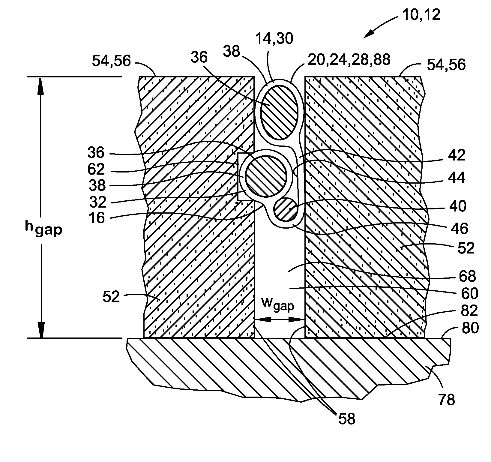
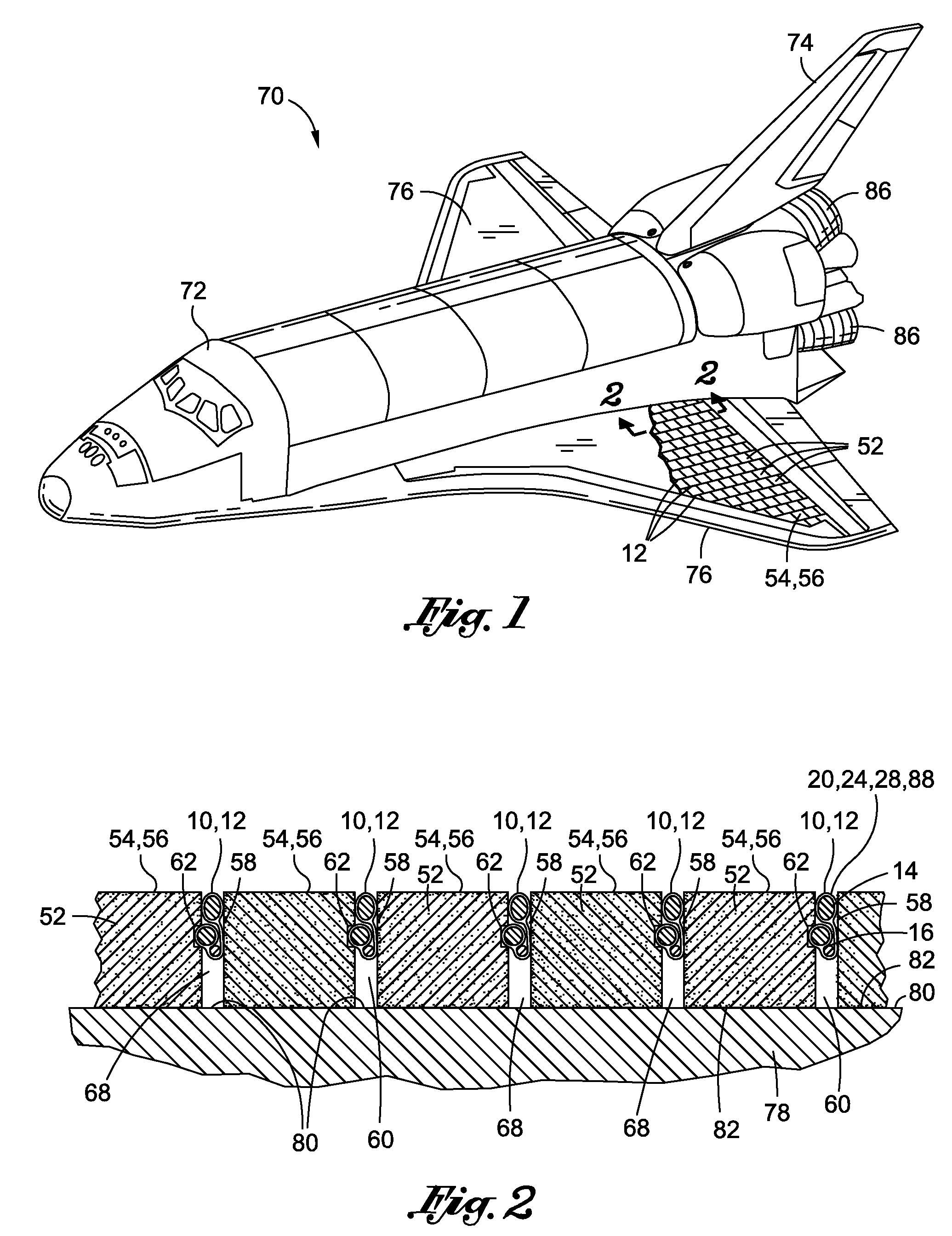
[0035]Referring now to the drawings wherein the showings are for purposes of illustrating preferred and various embodiments of the disclosure only and not for purposes of limiting the same, shown in FIG. 1 is a perspective illustration of a vehicle 70 which may employ one or more seal assemblies 12 for sealing tile gaps 60 between adjacently disposed tiles 52. The seal assembly 12 as disclosed herein may be installed within tile gaps 60 of tiles 52 mounted on a substructure 78 such as an airframe substructure 78 of the vehicle 70 illustrated in FIG. 1.

[0036]However, the seal assembly 12 may be installed within tile gaps 60 of tiles 52 that may be used in any application including, but not limited to, external surfaces of vehicles, internal surfaces of engines such as combustion chambers and nozzles in turbine and ramjet engines and nozzles in rocket engines as well as other high temperature environments. In this regard, the seal assembly 12 may be installed within tile gaps 60 of ti...


PUM


Abstract

A seal assembly is configured to seal a tile gap between a pair of tiles. Each of the tiles may include a tile side surface. At least one of the tiles may include a groove which may be formed along a length of the tile side surface. The seal assembly may comprise a gasket assembly including first and second bulb portions which may be interconnected by a web. A spacer rope may be positionable along the web. The gasket assembly may define a folded configuration for mounting within the tile gap when the web is wrapped around the spacer rope such that the second bulb portion is positioned between the spacer rope and the first bulb portion. The second bulb portion may be receivable within the groove.

Description

CROSS-REFERENCE TO RELATED APPLICATIONS[0001](Not Applicable)STATEMENT RE: FEDERALLY SPONSORED RESEARCH / DEVELOPMENT[0002](Not Applicable)FIELD[0003]The present disclosure relates generally to thermal protection systems and, more particularly, to a seal assembly and method for sealing gaps between tiles.BACKGROUND[0004]Thermal protection systems are employed in a wide variety of applications including, but not limited to, interior surfaces of jet and rocket engines and exterior surfaces of vehicles for protection against hot, convective flow passing over the vehicle. For example, a thermal protection system (TPS) may be applied to hypersonic vehicles and reusable launch vehicles to provide a thermal shield against extreme temperatures to which the vehicle is subjected. As applied to reusable launch vehicles, a TPS must be capable of protecting the vehicle substructure against temperature extremes ranging from −300° F. on orbit to 3000° F. during re-entry into the Earth's atmosphere. ...

Claims


Application Information

Patent Timeline
Patent Type & Authority Patents(United States)
IPC IPC(8): F16J15/02
CPCB64G1/58E04B1/948Y10S277/921
Inventor BEHRENS, WILLIAM W.TUCKER, ANDREW R.
Owner THE BOEING CO
Why Eureka
Try Eureka