Stuffing box for walking beam compressor

a technology of walking beam and packing box, which is applied in the direction of positive displacement liquid engines, liquid fuel engines, braking systems, etc., can solve the problems of requiring replacement and prone to wear

Inactive Publication Date: 2011-11-01
OIL FLOW USA
View PDF37 Cites 13 Cited by
  • Summary
  • Abstract
  • Description
  • Claims
  • Application Information

AI Technical Summary

Benefits of technology

[0006]The cylindrical seal can have a variety of configurations. In one embodiment, the cylindrical seal can be pre-disposed within the cavity, and any gaps formed between the cylindrical seal and an inner surface of the cylindrical housing are filled with additional injectable fibrous sealant injected into the lumen. In certain exemplary embodiments, the injectable fibrous sealant is under pressure when disposed within the lumen. The cylindrical seal can also include top and bottom pressure rings disposed on top and bottom end walls thereof and configured to prevent injectable fibrous sealant from leaking out of the lumen in the cylindrical housing. The top and bottom pressure rings can have, for example, a substantially A-shaped cross-section.
[0011]In other aspects, methods of manufacturing a piston rod seal assembly are provided, and in one embodiment the method can include forming a seal from an injectable fibrous sealant composition, positioning the seal within a housing, positioning a piston rod through the seal such that the piston rod is slidably movable relative to the housing and seal, and injecting additional injectable fibrous sealant composition into the housing to cause a pressurized seal to be formed around the piston rod. Injecting additional injectable fibrous sealant composition into the housing can fill all gaps between the seal, the housing, and the piston rod. In use, the seal can be configured to allow for longitudinal reciprocal movement of the piston rod therethrough while maintaining a gas-tight seal around the piston rod.
[0012]In one exemplary embodiment, forming a seal can include forming a cylindrical member having a bore formed therethrough. The cylindrical member can have a width from an outer surface to an inner surface thereof that corresponds to a distance between an interior wall of the housing and the piston rod. The method can also include mating top and bottom pressure rings to the seal. The pressure rings can prevent the injectable fibrous sealant composition from leaking out of the housing. Top and bottom washers can also be positioned adjacent to the top and bottom pressure rings. The method can further include coupling the housing to a compressor and coupling the piston rod to a walking beam that pumps oil out of the ground.

Problems solved by technology

Traditionally, a piston rod seal may have rubber sealing elements that tend to wear quickly and require replacement.

Method used


Image

  • Stuffing box for walking beam compressor
  • Stuffing box for walking beam compressor
  • Stuffing box for walking beam compressor

Examples


Embodiment Construction

[0022]Certain exemplary embodiments will now be described to provide an overall understanding of the principles of the structure, function, manufacture, and use of the devices and methods disclosed herein. One or more examples of these embodiments are illustrated in the accompanying drawings. Those skilled in the art will understand that the devices and methods specifically described herein and illustrated in the accompanying drawings are non-limiting exemplary embodiments and that the scope of the present invention is defined solely by the claims. The features illustrated or described in connection with one exemplary embodiment may be combined with the features of other embodiments. Such modifications and variations are intended to be included within the scope of the present invention.

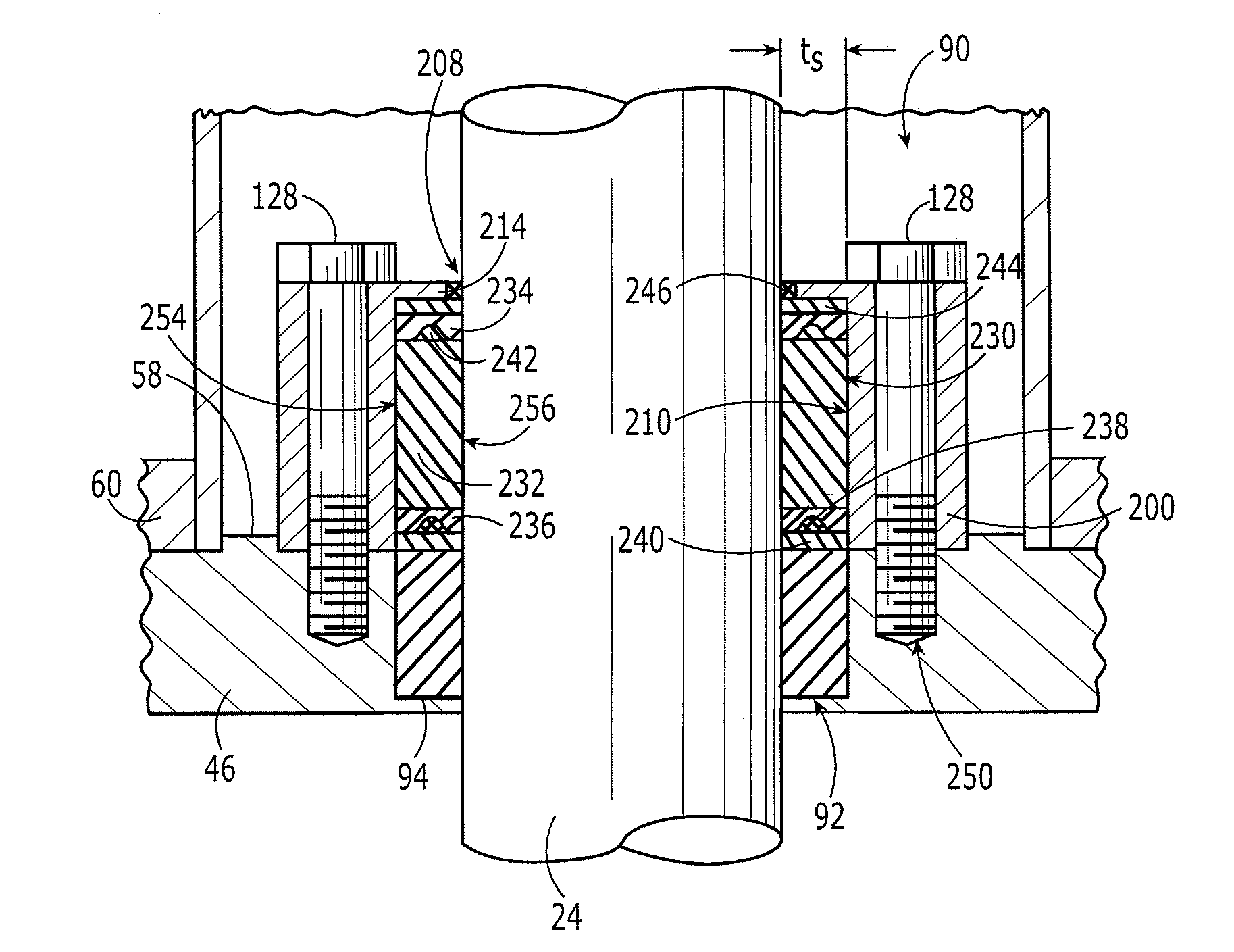
[0023]The present invention generally provides a piston rod seal assembly for use in a walking beam compressor and methods for manufacturing the same. In general, the piston rod seal assembly includes...


PUM

PropertyMeasurementUnit
diameteraaaaaaaaaa
pressureaaaaaaaaaa
shapeaaaaaaaaaa

Abstract

Various methods and devices are provided for use in a walking beam compressor used with an oil well pump. In general, an injectable fibrous sealant is provided for use in a stuffing box to form a seal around a piston rod that couples to a walking beam for pumping oil out of the ground. The injectable fibrous sealant can be configured to form a gas tight seal around the piston rod, while allow reciprocal longitudinal movement of the piston rod therethrough. The injectable fibrous sealant is particularly advantageous as it has an extended life, eliminating the need to replace the seal, and repairs can be performed on-site by injecting additional sealant into the stuffing box.

Description

FIELD OF THE INVENTION[0001]The present invention relates to gas compressors to be used with oil wells, and in particular to a piston rod seal assembly for use in a walking beam compressor and methods for manufacturing the same.BACKGROUND OF THE INVENTION[0002]A common oil well pumping system includes a walking beam mounted upon a horizontally-axised, transverse pivot at the top of a Samson post. One end of the walking beam is connected to a pump rod and the other end is connected to the crank of a drive motor through a connecting rod. Rotation of the crank causes the walking beam to rock or oscillate in a vertical plane to raise and lower the pump rod. The rod-connected end of the walking beam is provided with the familiar “horse head” to keep the pump rod in alignment with the well axis. The opposite end of the walking beam carries a counterbalance weight to offset the weight of the pump rod and minimize the stress on the motor.[0003]When pumping an oil well, both oil and gas may ...

Claims


Application Information

Patent Timeline
Patent Type & Authority Patents(United States)
IPC IPC(8): F04B53/00F16J15/18
CPCF04B47/00F04B53/164Y10T29/49236Y10T29/49277
Inventor MERRICK, III, WARD S.
Owner OIL FLOW USA
Why Eureka
Try Eureka