
Battery pack cooling system for vehicle

a battery pack and cooling system technology, applied in the direction of battery/fuel cell control arrangement, battery/cell components, propulsion by batteries/cells, etc., can solve the problems of large amount of heat generated by unit cells, degraded unit cells, and air pollution, so as to reduce the flow speed of metal dust, effectively collect metal dust, and increase the collecting efficiency

Active Publication Date: 2011-11-01
LG ENERGY SOLUTION LTD
View PDF20 Cites 10 Cited by
  • Summary
  • Abstract
  • Description
  • Claims
  • Application Information

AI Technical Summary

Benefits of technology

The present invention provides a cooling system for vehicle battery packs that improves cooling efficiency through the use of a double filter device that can filter fine dust and metal dust from air. The system uses air existing at a region around the battery pack as a coolant, which prevents the air from being recirculated and reduces the possibility of malfunctions or short circuits. The system also eliminates the need for a pipe-shaped intake duct, which reduces noise and backward flow of flames and toxic gas. The system includes a pre-filter and a medium filter with relatively large air holes, which are replaced with high frequency to extend the cooling cycle and reduce costs. The magnetic force applied to the filters helps to collect metal dust, which prevents malfunctions or short circuits. The system also utilizes air existing inside the vehicle to cool the battery pack, which further improves cooling efficiency.

Problems solved by technology

One of the biggest problems caused from vehicles using fossil fuel, such as gasoline and diesel oil, is creation of air pollution.
In such a high-output, large-capacity secondary battery, however, a large amount of heat is generated from the unit cells during the charge and the discharge of the unit cells.
When the heat generated from the unit cells during the charge and the discharge of the unit cells is not effectively removed, heat is accumulated in the unit cells with the result that the unit cells are degraded.
Such dust may cause a serious problem especially in a fuel cell, which uses air as one of material components for battery operation.
Consequently, seriousness of problems due to dust in the case of the battery pack is lower than that in the case of the fuel cell.
However, when such fine dust is introduced into the battery pack along with the air, and, as a result, the dust is excessively accumulated on unit cells of the battery pack, the cooling efficiency is decreased.
Furthermore, when metal dust component among the fine dust is accumulated on an electrical connecting part and a circuit board of the battery pack, the malfunction or short circuits of the battery pack may be caused.
However, the detailed construction of the filter is not disclosed in the patents.
In this case, various-sized dust is filtered by the single filter with the result that the filter replacing cycle is very short.
Also, an expensive filter is needed to filter fine dust.
Especially, it is difficult to remove metal dust, which may cause the malfunction or short circuits of the battery pack.

Method used


Image

  • Battery pack cooling system for vehicle
  • Battery pack cooling system for vehicle
  • Battery pack cooling system for vehicle

Examples


Embodiment Construction

[0038]Now, preferred embodiments of the present invention will be described in detail with reference to the accompanying drawings. It should be noted, however, that the scope of the present invention is not limited by the illustrated embodiments.

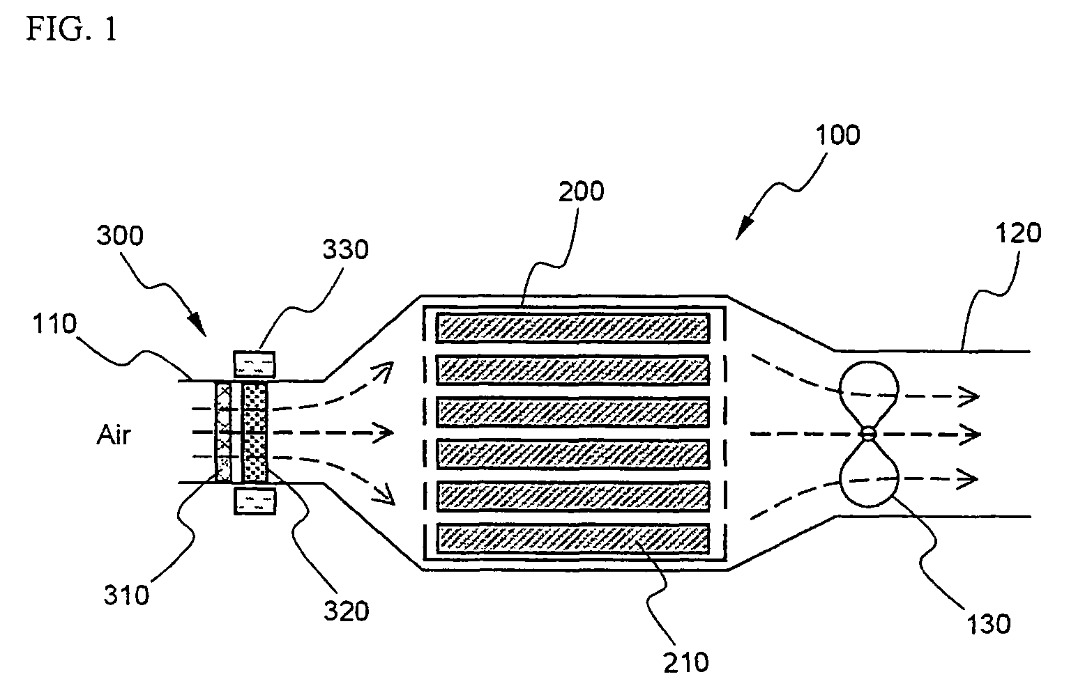
[0039]FIG. 1 is a typical view illustrating the structure of a cooling system for vehicle battery packs according to a preferred embodiment of the present invention.

[0040]Referring to FIG. 1, the cooling system 100 comprises a front air inlet part 110, through which air is introduced toward a battery pack 200 including a plurality of unit cells 210, a rear air outlet part 120, through which the air having passed through the battery pack 200, which has been heated, is discharged, and a cooling fan 130 for driving air to be introduced and discharged.

[0041]At the air inlet part 110 is mounted a double filter device 300 comprising a pre-filter 310 having relatively large air holes and a medium filter 320 having relatively small air holes. A magn...


PUM

PropertyMeasurementUnit
frequencyaaaaaaaaaa
shapeaaaaaaaaaa
temperatureaaaaaaaaaa

Abstract

Disclosed herein is a cooling system for vehicle battery packs, including a double filter device mounted at an air inlet part, through which air for cooling the battery pack is introduced from the outside and / or the inside of the vehicle. The double filter includes a pre-filter having relatively large air holes, the pre-filter having high frequency of replacement, and a medium filter having relatively small air holes, the medium filter having low frequency of replacement. The pre-filter is located before the medium filter in the direction in which the air is introduced. Consequently, dust is removed from air, and therefore, the cooling efficiency of the battery pack is increased. In a preferred structure, metal dust is also effectively removed by the magnetic force applied to the medium filter. Consequently, the malfunction or short circuits of the battery pack are prevented. Also, air surrounding the battery pack is directly introduced through the through-type intake ports without passing through any pipe-shaped intake duct. Consequently, generation of noise, which is a problem caused when air in the cabin is used, and backward flow of flames and toxic gas, which are generated during a fire, are prevented. Furthermore, the battery pack is constructed in a compact structure.

Description

FIELD OF THE INVENTION[0001]The present invention relates to a cooling system for vehicle battery packs, which are used as a power source for electric vehicles and hybrid electric vehicles, and, more particularly, to a cooling system for vehicle battery packs, including a pre-filter having high frequency of replacement and a medium filter having low frequency of replacement, which are successively mounted at an air inlet part, through which air for cooling the battery pack is introduced from the outside or the inside of the vehicle, thereby effectively removing dust from the air, and therefore, preventing reduction of the cooling efficiency due to excessive accumulation of the dust, and preventing the malfunction or short circuits of the battery pack due to contamination of an electrical connecting part and a circuit board.BACKGROUND OF THE INVENTION[0002]One of the biggest problems caused from vehicles using fossil fuel, such as gasoline and diesel oil, is creation of air pollution...

Claims


Application Information

Patent Timeline
Patent Type & Authority Patents(United States)
IPC IPC(8): H01M10/50B60R16/04B60K11/06H01M50/204
CPCB60L11/1874B60L11/1877B60L11/1879H01M2/1072H01M10/5016H01M10/5067H01M10/5004Y02T10/705Y02T10/7005H01M10/625H01M10/6563H01M10/613B60L58/26B60L50/66B60L50/64Y02T10/70Y02E60/10H01M50/204
Inventor YANG, JAE HUN
Owner LG ENERGY SOLUTION LTD
Learn More