Conveyor drive control system

a control system and conveyor technology, applied in the field of conveyor drive control system, can solve the problems of erratically advancing conveyor chains, affecting the efficiency inefficient operation of drive motors in any given zone along the conveyor line, so as to increase the likelihood of erratic performance, increase the number of drives, and prolong the chain

Inactive Publication Date: 2011-11-01
NEUMANN LINDA E
View PDF18 Cites 15 Cited by
  • Summary
  • Abstract
  • Description
  • Claims
  • Application Information

AI Technical Summary

Benefits of technology

[0003]A common type of conveyor system is a monoveyor which can transport a load or series of loads on carriers that are directly attached to the chain of the conveyor system. Another common type of chain conveyor is a “power & free” system. As with the monoveyor systems, the primary moving element is a chain, however, in this case the chain is utilized to push detached carriers along the path of the conveyor. These detached carriers are located in a separate “free rail”. Mechanisms along the pathway of the conveyor allow the carrier to disengage, stop, and switch to different pathways of the conveyor system. The load in either of these systems can be a work piece that needs to be delivered to various work stations in order for particular operations to be performed such as machining, and once machined, the work piece continues on the conveyor to the next station. Multi-drive systems are commonly used to deliver power and movement to these conveyors.
[0006]Presently, a number of control technologies are employed to allow multi-drive systems to perform the required work. All systems rely to some degree on motor “slip” to balance the relative torque demands during operation. Some systems utilize torque feedback techniques to adjust individual motor torque outputs. In any case, the individual drive control systems “react” to the imposed load conditions. For this reason, chain conveyors are designed with the limitations imposed by reactive drive systems in mind. With the current available technologies employed, the longer the chain and the greater the quantity of drives utilized in a multi-drive system, the higher the likelihood of erratic performance. Therefore multi-drive conveyors are avoided when possible. The present invention overcomes this problem.
[0008]Therefore, it would be desirable to provide a conveyor drive control system that overcomes the aforementioned problems. The preferred system should be dynamic and operable to constantly change performance output of every motor within the system, in view of the constantly changing loads on the system. It would also be desirable to provide a drive control system that improves the available technology such that torque demands on the drive system are anticipated and proactively met, speed requirements are maintained, and in addition, total continuous chain length may be effectively increased well beyond the 2000 foot limitation so as to accommodate the total length of the work zone of the conveyor.
[0010]It would also be desirable to provide an improved drive control system that improves delivery of balanced power and speed control throughout the multi-drive material handling system. It would also be beneficial to increase the work efficiency of these systems by reducint the amount and weight of the “return chain” of power & free systems, extending the total work length of the chain, as well as a reduction in the total number of drives required to move all loads along the path of the conveyor system so as to provide cost savings.
[0012]One aspect of the present invention provides a drive control system for a conveyor comprising one or more variable speed motors for driving a conveyor device. A dynamic chain pull calculation program is operable to continuously calculate the torque requirements for each motor in the system. One or more sensors are employed that are operable to create a signal indicative of a load transiting a designated zone and, if required, additional data including the weight of such a load or loads, and send data to a PLC. The PLC then converts the data from each sensor and transmits a signal to a computer operating the dynamic chain pull calculation program. A computer is operable to process the signal from the PLC using the dynamic chain pull calculation program and in turn generates real time drive torque data for each motor. A motor controller is operable to control each variable speed motor within the system so that the proper torque is generated by each motor as is required for optimum performance. The resulting drive control system is dynamic and continuously monitors torque requirements for each motor within the system given current load data so as to maximize efficiency of the conveyor.

Problems solved by technology

The problem however is that traditional multi-drive systems do not compensate well under all conditions for the changes in torque demand as loads advance along the conveyor line.
This may cause the drive motor in any given zone along the conveyor line to operate inefficiently.
By contrast, a different drive motor in another zone that is temporarily carrying very little load could be over performing and producing too much torque output thus causing the conveyor chain and thus the carriers and loads to advance along the conveyor line erratically.
This inconsistency amongst the zones can also cause undue stress on the components of the conveyor.
With the current available technologies employed, the longer the chain and the greater the quantity of drives utilized in a multi-drive system, the higher the likelihood of erratic performance.
Operational irregularities can result due to chain speed inconsistencies that can affect both manual and automatic systems interfacing with the conveyor and in some cases can present a safety hazard or cause negative quality impacts on product within a plant or conveyor line.

Method used


Image

  • Conveyor drive control system
  • Conveyor drive control system
  • Conveyor drive control system

Examples


Embodiment Construction

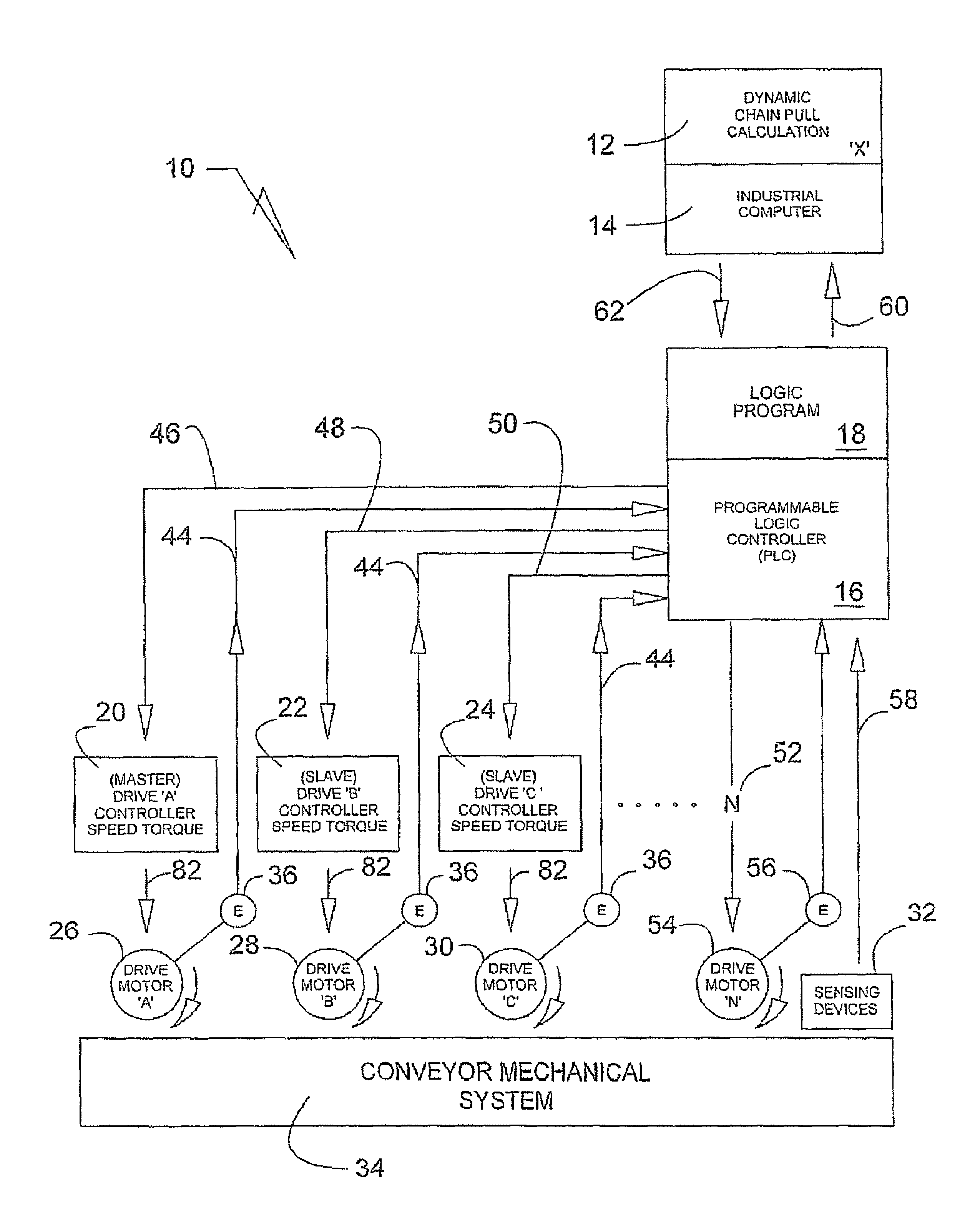
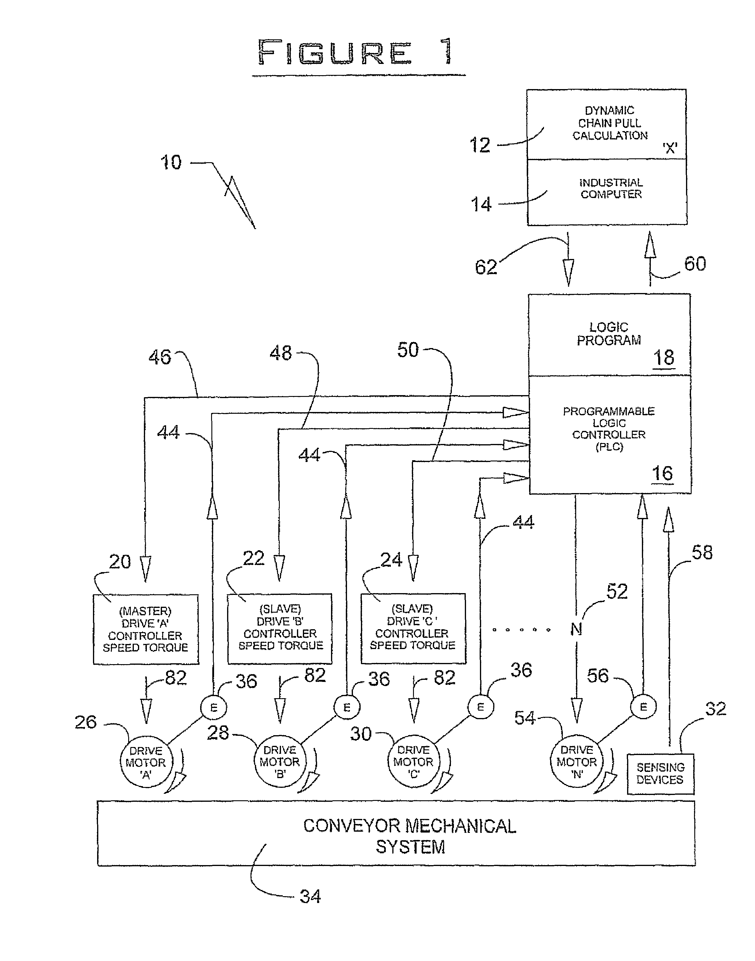
[0017]A drive control system 10 is illustrated in FIG. 1 and includes a dynamic chain pull calculation computer software program 12, and industrial computer 14, a PLC 16 with software 18, a plurality of drive controllers 20, 22 and 24, a plurality of drive motors 26, 28 and 30 and sensing devices 32. The drive control system 10 is integrated with a conveyor 34 which includes typical components for moving work pieces throughout an assembly line. It will be appreciated that the present drive control system 10 can be utilized wherever it is desired to dynamically control the movement of material from place to place.

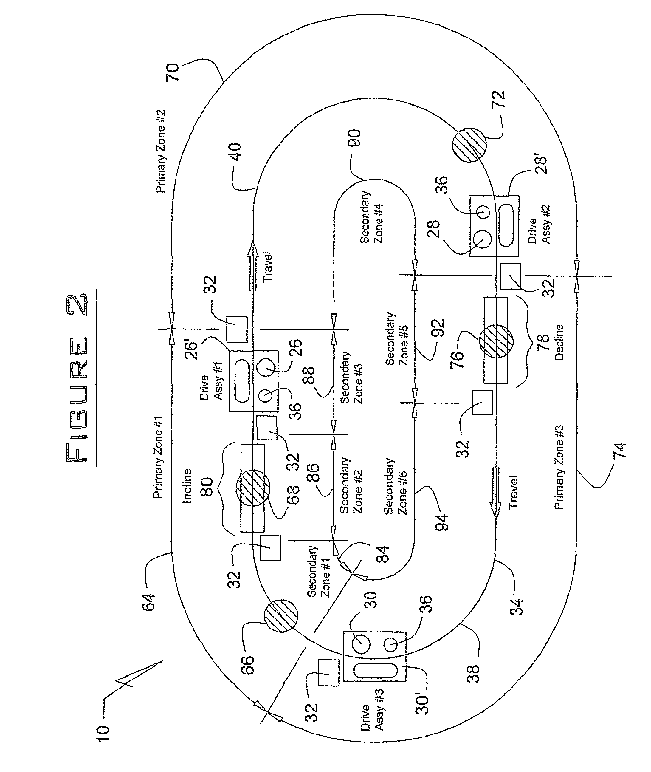
[0018]With continued reference to FIG. 1, an individual encoder 36 is places in proximity to drive motors 26, 28 and 30 for counting and monitoring the links 38 that comprise a conveyor or chain 40. The conveyor chain can be in excess of the 2,000 ft. limitation that is typically ascribed to chain conveyor applications. Through utilization of the encoders 36, the specific nu...


PUM


Abstract

A drive control system for conveyor utilizes a dynamic chain pull calculation program that is integrated with a PLC, which communicates to a plurality of controllers. The controllers in turn automatically adjust their associated drive motors so as to maximize efficiency at moving material on a conveyor system. Sensing devices provide continuous load parameters to a PLC that in turn, processes the data and adjusts the system's operation based upon desired conditions.

Description

FIELD OF THE INVENTION[0001]A drive control system for use in connection with a conveyor that can be used in a manufacturing operation, more specifically, a dynamic conveyor drive control system that employs a mathematical model to effectuate delivery of balanced power and speed control of a material handling system so as to maximize efficiency of moving work material throughout a production facility.BACKGROUND AND SUMMARY OF THE INVENTION[0002]It is well known to provide a conveyor to move material throughout a plant. In many instances, electric motors are utilized to drive a chain which in turn is routed throughout a manufacturing line or plant so as move a part (load) along a predetermined path. The weight of the load(s) to be carried by a conveyor system are normally predetermined and are factored into a formula for ascertaining the torque requirements for a given drive motor or set of drive motors that are required to move all anticipated loads at a given speed. Sensing devices...

Claims


Application Information

Patent Timeline
Patent Type & Authority Patents(United States)
IPC IPC(8): G06F7/00
CPCB65G43/08G05B19/4189G05B2219/41112G05B2219/45054Y02P90/02
Inventor DOLLENS, DONALD
Owner NEUMANN LINDA E
Why Eureka
Try Eureka