Dynamic bias supply devices

a supply device and bias technology, applied in the direction of rf amplifiers, amplifier combinations, high frequency amplifiers, etc., can solve the problems of non-linearity and efficiency deterioration, performance deterioration, and high linearity, and achieve high linearity and high efficiency of power amplifiers.

Active Publication Date: 2011-11-08
RES & BUSINESS FOUND SUNGKYUNKWAN UNIV
View PDF6 Cites 57 Cited by
  • Summary
  • Abstract
  • Description
  • Claims
  • Application Information

AI Technical Summary

Benefits of technology

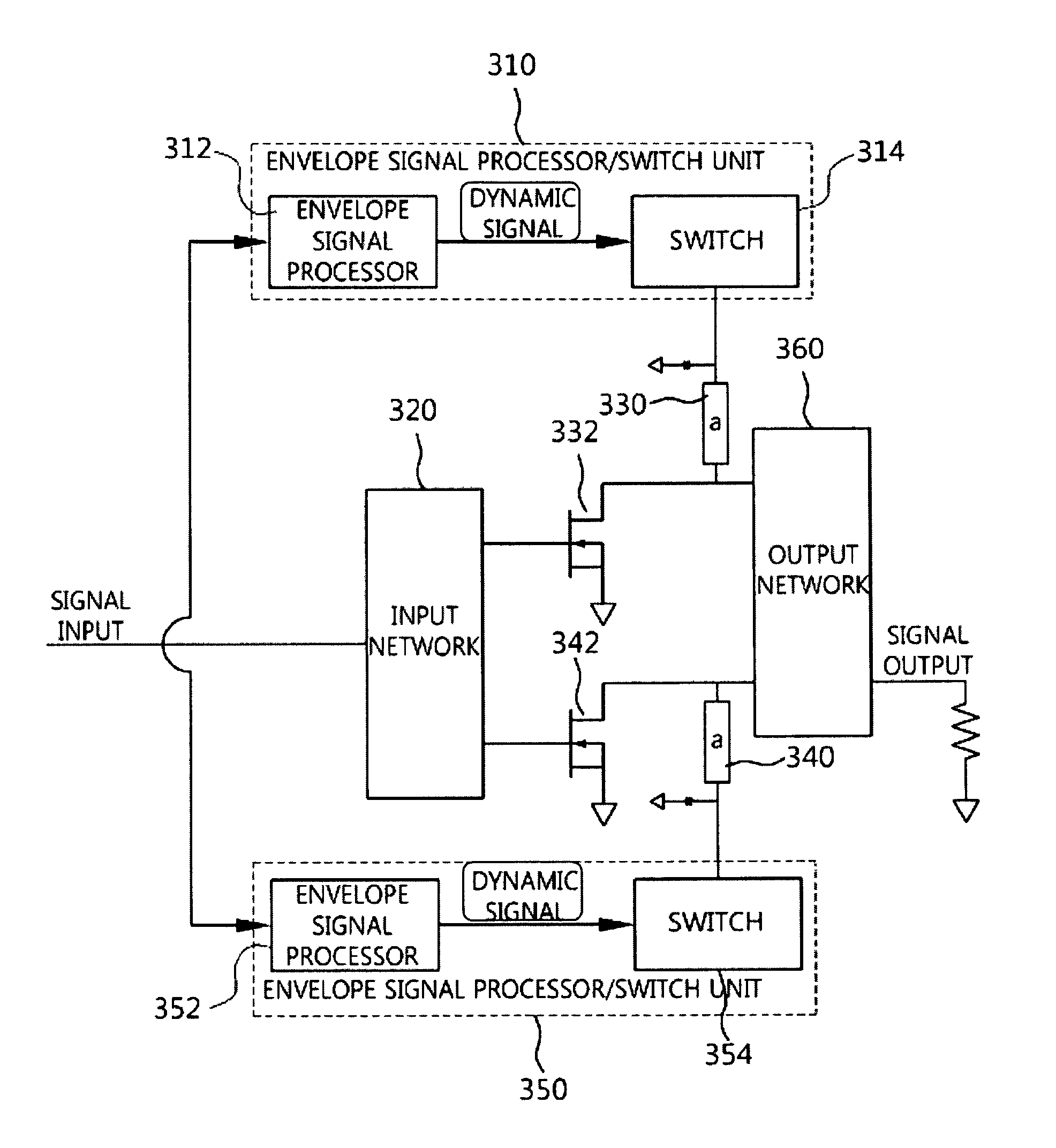
[0024]Example embodiments of the present invention provide multiple parallel power amplifiers employing a dynamic bias supply device having multiple switches to remove an unnecessarily generated performance deterioration factor and achieve high efficiency and high linearity of the power amplifiers.

Problems solved by technology

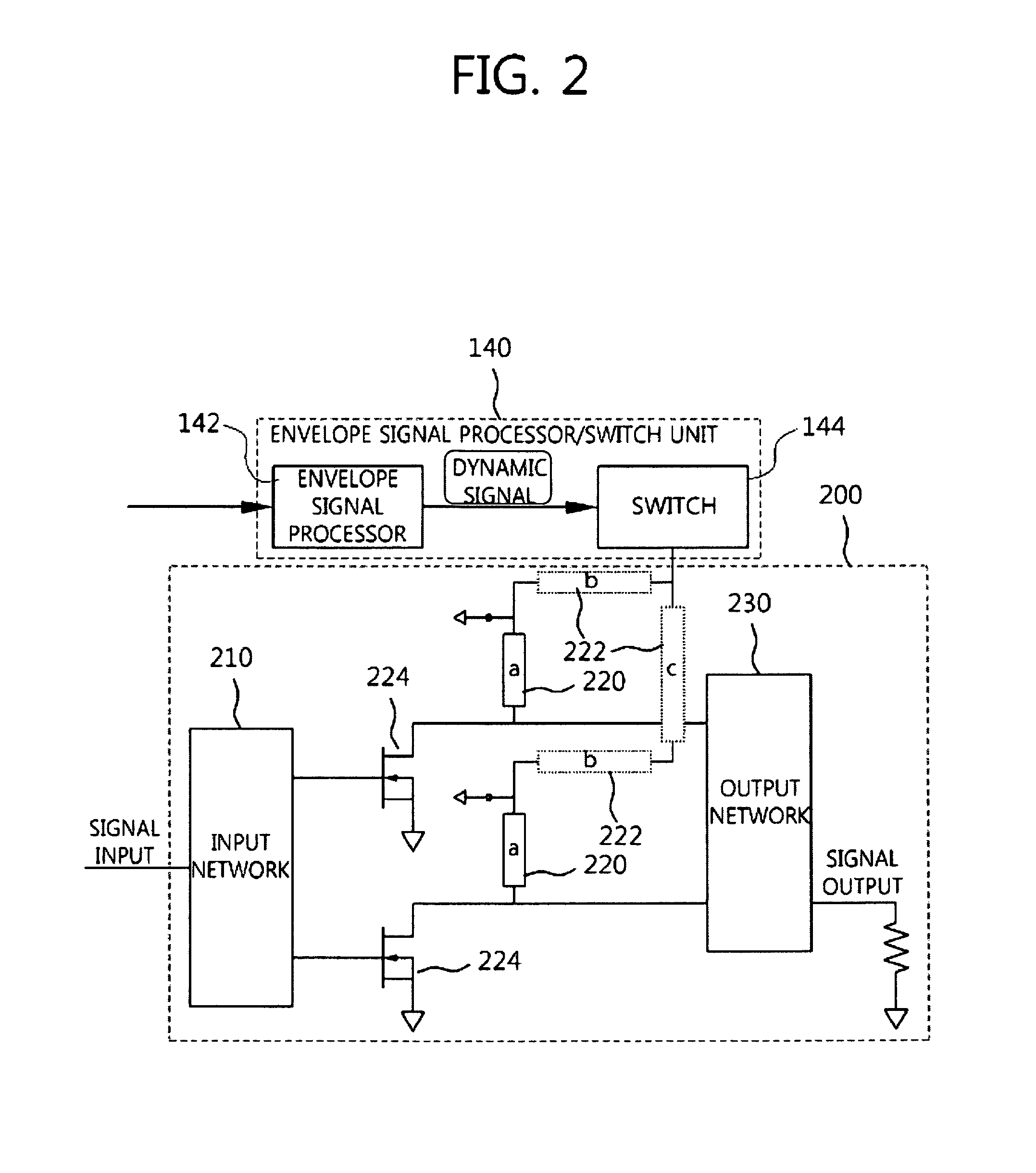
When such unnecessary lines cause a mismatch between power amplifiers 224, the mismatch causes performance deterioration, such as a memory effect, non-linearity and efficiency deterioration, and high linearity and high efficiency are deteriorated.
However, when each of the constitutions is installed in multiple parallel power amplifiers as a single dynamic bias supply device, the constitution deteriorates high linearity and high efficiency.

Method used


Image

  • Dynamic bias supply devices
  • Dynamic bias supply devices
  • Dynamic bias supply devices

Examples


Embodiment Construction

[0036]Example embodiments of the present invention are disclosed herein. However, specific structural and functional details disclosed herein are merely representative for purposes of describing example embodiments of the present invention, however, example embodiments of the present invention may be embodied in many alternate forms and should not be construed as limited to example embodiments of the present invention set forth herein.

[0037]Accordingly, while the invention is susceptible to various modifications and alternative forms, specific embodiments thereof are shown by way of example in the drawings and will herein be described in detail. It should be understood, however, that there is no intent to limit the invention to the particular forms disclosed, but on the contrary, the invention is to cover all modifications, equivalents, and alternatives falling within the spirit and scope of the invention. Like numbers refer to like elements throughout the description of the figures...


PUM


Abstract

A dynamic bias supply device for multiple parallel power amplifiers, in which a plurality of parallel power amplifiers including a Doherty amplifier are connected in parallel, is provided. The dynamic bias supply device includes a plurality of switches respectively corresponding to each of the parallel power amplifiers. The dynamic bias supply device is used in a distributed manner as multiple distributed dynamic bias switching circuits for the multiple parallel power amplifiers. Accordingly, performance deterioration is not caused by an additional connection structure, and it is possible to achieve high efficiency and high linearity of the power amplifiers.

Description

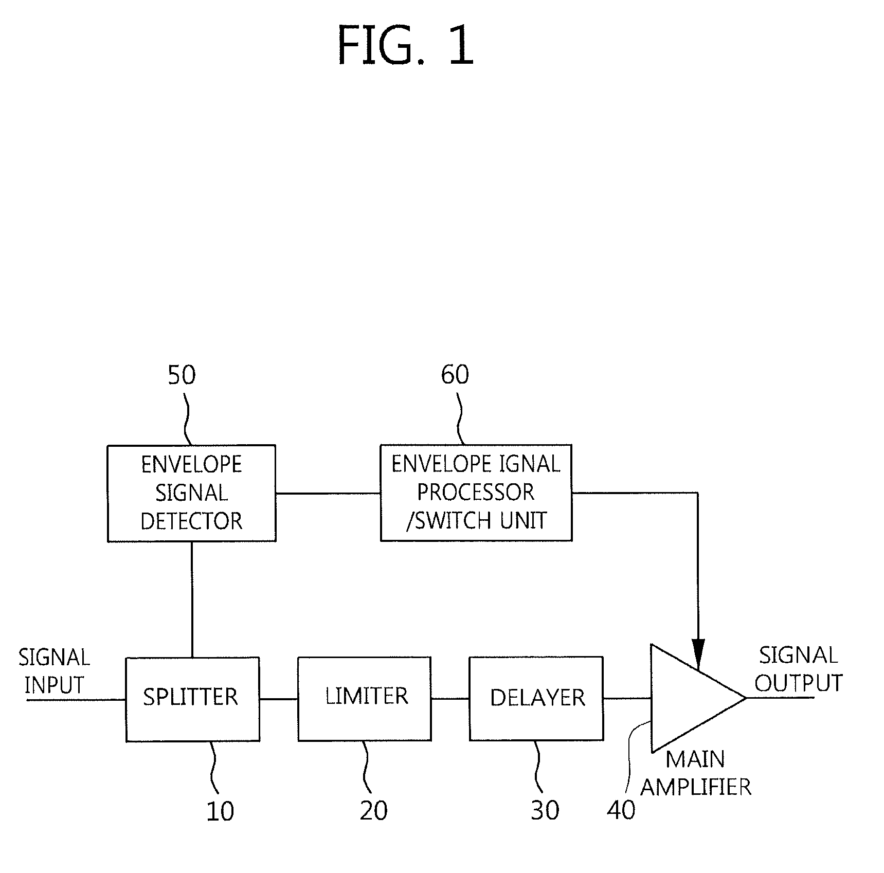
CLAIM FOR PRIORITY[0001]This application claims priority to Korean Patent Application No. 10-2009-67212 filed on Jul. 23, 2009 in the Korean Intellectual Property Office (KIPO), the entire contents of which are hereby incorporated by reference.BACKGROUND[0002]1. Technical Field[0003]Example embodiments of the present invention relate in general to devices for providing bias to a base station power amplifier or a terminal power amplifier used for high efficiency and high linearity in radio communications.[0004]2. Related Art[0005]Various circuits and devices for dynamic bias of power amplifiers are known. Such a dynamic bias switching circuit switches dynamic bias to a power amplifier.[0006]FIG. 1 is a block diagram of a general dynamic bias switching device.[0007]FIG. 1 illustrates an example of the structure of a device conventionally suggested to supply dynamic bias to a power amplifier. The device provides an input signal to a main path (a limiter 20, a delayer 30, and a main amp...

Claims


Application Information

Patent Timeline
Patent Type & Authority Patents(United States)
IPC IPC(8): H03F3/68
CPCH03F1/0266H03F1/0277H03F1/0288H03F1/3205H03F1/56H03F3/189H03F3/211H03F3/24H03F2200/102H03F2200/222H03F2200/27H03F2200/387H03F2200/451H03F2203/21142H03F1/02H03F1/30H03F3/68
Inventor YANG, YOUNGOOKIM, MIN-SU
Owner RES & BUSINESS FOUND SUNGKYUNKWAN UNIV
Why Eureka
Try Eureka