Optical device and associated methods

a technology of optical devices and optical characteristics, applied in the field of optical devices, can solve the problems of increased non-uniformity of lenses, increased material weight, and increased material weight,

Active Publication Date: 2011-11-08
FLIR SYSTEMS TRADING BELGIUM BVBA
View PDF12 Cites 5 Cited by
  • Summary
  • Abstract
  • Description
  • Claims
  • Application Information

AI Technical Summary

Benefits of technology

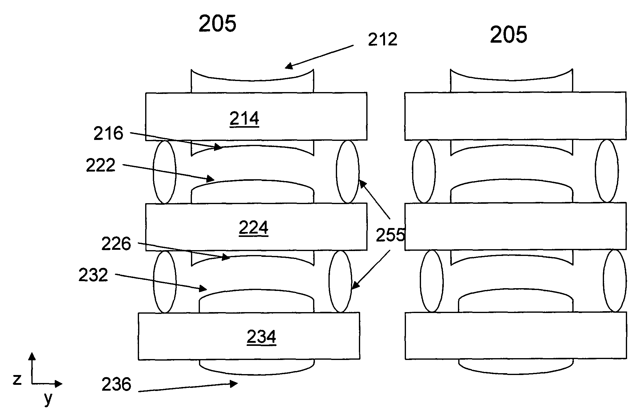
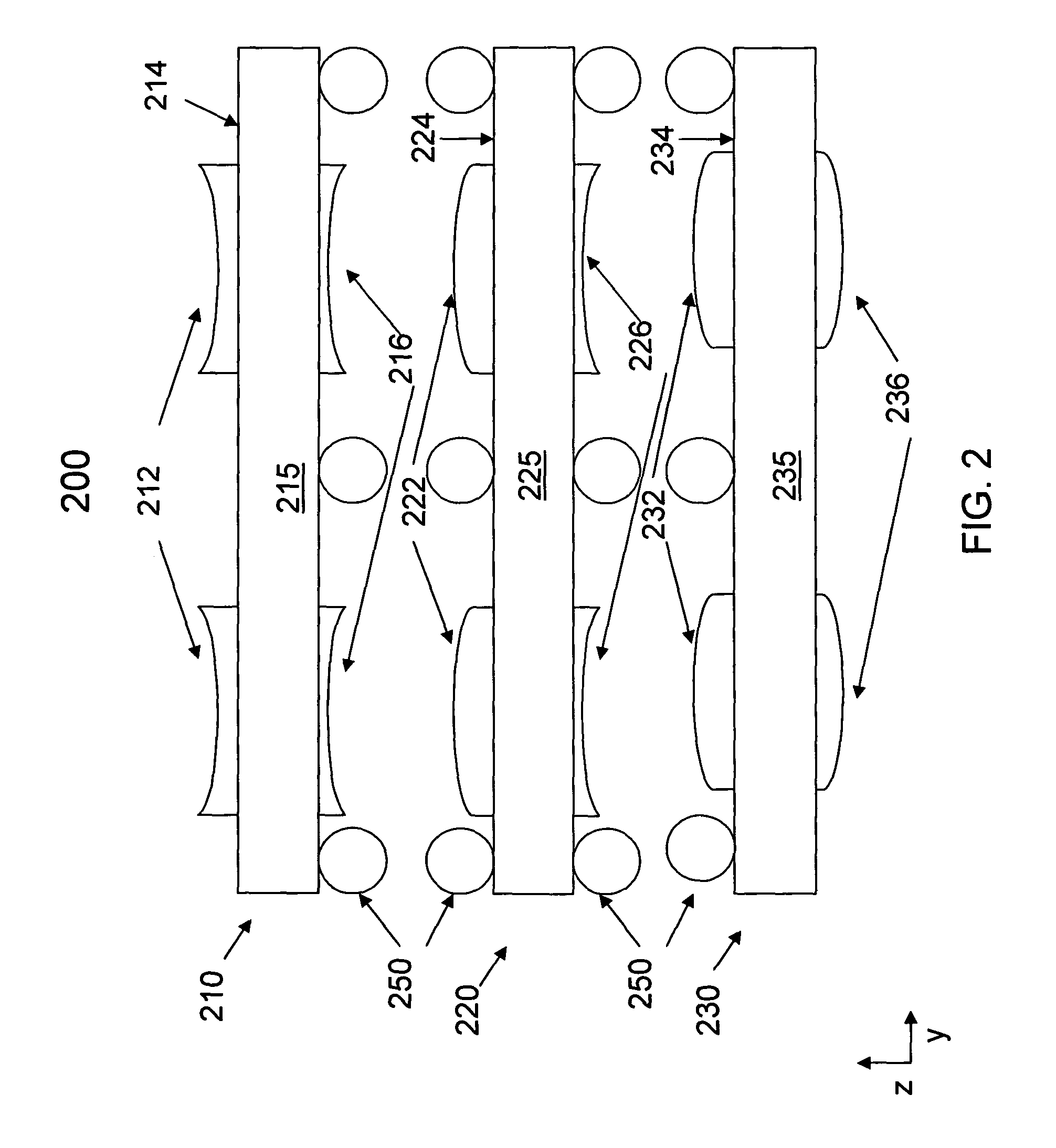
[0009]It is another feature of an embodiment to create an optical device and associated methods in which multiple surface structures having improved optothermal performance.
[0010]It is yet another feature of an embodiment to create an optical device and associated methods in which a number of structures needed to realize a particular output may be reduced.
[0013]The material and curvature of the first replicated surface and the material and curvature of the second replicated surface may be configured to substantially reduce the chromatic dispersion of the optical device and / or to substantially reduce the thermal sensitivity of the optical device.
[0019]At least one of the above and other features and advantages may be realized by providing an optical device, including a first surface in a first material having a first coefficient of optothermal expansion and a second surface in a second material having a second coefficient of optothermal expansion on the first surface, the second surface having a radius of curvature, the first and second surfaces being designed to substantially reduce the chromatic dispersion for the optical device.

Problems solved by technology

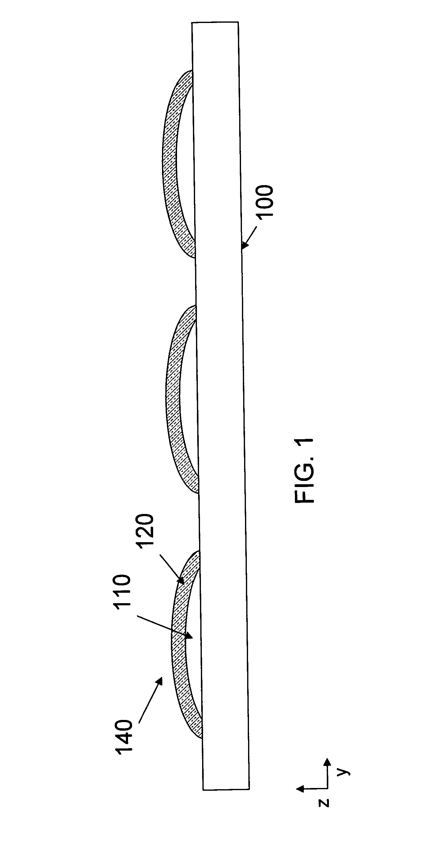
There are advantages and disadvantages to most types of materials used to make optical surfaces, i.e., surfaces having optical power, both in manufacturing and performance.
However, such materials may suffer from high temperature dependence of optical characteristics, e.g., refractive index, and mechanical characteristics, e.g., surface shape.
Further, when a thickness of polymer material needed to create a specific lens design increases, excessive shrinkage and shape deformation may occur.
In contrast, while glass has a relatively low coefficient of thermal expansion (CTE) and a low optical thermal coefficient, when sags of glass lenses increases and a number of lenses to be created simultaneously increases, non-uniformity of the lenses may increase, reducing yield depending upon manufacturing techniques employed.
However, such structures are not made monolithically and are thus expensive to manufacture, particularly in small form factors.

Method used


Image

  • Optical device and associated methods
  • Optical device and associated methods
  • Optical device and associated methods

Examples


Embodiment Construction

[0027]Example embodiments will now be described more fully hereinafter with reference to the accompanying drawings; however, they may be embodied in different forms and should not be construed as limited to the embodiments set forth herein. Rather, these embodiments are provided so that this disclosure will be thorough and complete, and will fully convey the scope of the invention to those skilled in the art.

[0028]In the figures, the dimensions of layers and regions may be exaggerated for clarity of illustration. It will also be understood that when a layer or element is referred to as being “on” another layer or substrate, it can be directly on the other layer or substrate, or intervening layers may also be present. Further, it will be understood that when a layer is referred to as being “under” another layer, it can be directly under, and one or more intervening layers may also be present. In addition, it will also be understood that when a layer is referred to as being “between” ...


PUM


Abstract

An optical device includes a transparent substrate, a first replicated refractive surface on a first surface of the substrate in a first material, and a second replicated refractive surface on a second surface, opposite the first surface, and made of a second material, different from the first material. The material and curvature of the first replicated surface and the material and curvature of the second replicated surface may be configured to substantially reduce the chromatic dispersion and / or the thermal sensitivity of the optical device.

Description

BACKGROUND[0001]1. Field of the Invention[0002]Embodiments are directed to an optical device and associated methods. More particularly, embodiments are directed to an optical device having enhanced performance and associated methods.[0003]2. Description of Related Art[0004]There are advantages and disadvantages to most types of materials used to make optical surfaces, i.e., surfaces having optical power, both in manufacturing and performance. For example, polymer materials may allow a wide variety of shapes to be accurately realized, and may provide more degrees of freedom in making wafer based optical elements. However, such materials may suffer from high temperature dependence of optical characteristics, e.g., refractive index, and mechanical characteristics, e.g., surface shape. Further, when a thickness of polymer material needed to create a specific lens design increases, excessive shrinkage and shape deformation may occur. In contrast, while glass has a relatively low coeffici...

Claims


Application Information

Patent Timeline
Patent Type & Authority Patents(United States)
IPC IPC(8): G02B11/00G02B1/00B31B50/62
CPCB29D11/00298G02B13/0085G02B27/0025H01L27/14625G02B7/028G02B13/006Y10T156/10H01L27/14618H01L2924/0002H01L2924/00
Inventor KATHMAN, ALAN
Owner FLIR SYSTEMS TRADING BELGIUM BVBA
Why Eureka
Try Eureka