

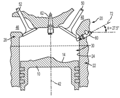
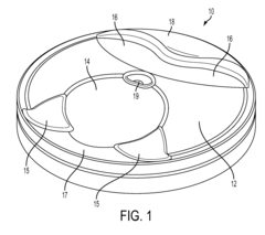
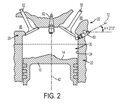
Shallow piston bowl and injector spray pattern for a gasoline, direct-injection engine
a gasoline, direct-injection technology, applied in the direction of machines/engines, mechanical equipment, output power, etc., can solve the problems of poor fuel-air mixing of gdi engines, insufficient time for vaporization and complete mixing, and inability to achieve complete mixing,
- Summary
- Abstract
- Description
- Claims
- Application Information
AI Technical Summary
Benefits of technology
Problems solved by technology
Method used
Image

Examples
Embodiment Construction
[0015]As those of ordinary skill in the art will understand, various features of the embodiments illustrated and described with reference to any one of the Figures may be combined with features illustrated in one or more other Figures to produce alternative embodiments that may not be explicitly illustrated or described. The combinations of features illustrated provide representative embodiments for typical applications. However, various combinations and modifications of the features consistent with the teachings of the present disclosure may be desired for particular applications or implementations. The representative embodiments used in the illustrations relate generally to a four-stroke, multi-cylinder, direct-injected, spark-ignition internal combustion engine having an in-line configuration. Those of ordinary skill in the art may recognize similar applications or implementations with other engine / vehicle technologies and configurations including but not limited to in-line confi...
PUM
| Property | Measurement | Unit |
|---|---|---|
| angle | aaaaa | aaaaa |
| diameter | aaaaa | aaaaa |
| diameter | aaaaa | aaaaa |
Abstract
Description
Claims
Application Information