Internal combustion engine having an electric solenoid poppet valve and air/fuel injector

Inactive Publication Date: 2011-11-15
DONICK ENGINES
View PDF24 Cites 17 Cited by
  • Summary
  • Abstract
  • Description
  • Claims
  • Application Information

AI Technical Summary

Benefits of technology

[0003]The present invention is a internal combustion engine having a unique Electric Magnetic Solenoids to operate the single poppet valve in each cylinder. The spark plug is located in the cylinder head in a position to allow t

Problems solved by technology

However on the intake stroke of the engine, the piston still has to draw fuel from t

Method used


Image

  • Internal combustion engine having an electric solenoid poppet valve and air/fuel injector
  • Internal combustion engine having an electric solenoid poppet valve and air/fuel injector
  • Internal combustion engine having an electric solenoid poppet valve and air/fuel injector

Examples


Embodiment Construction

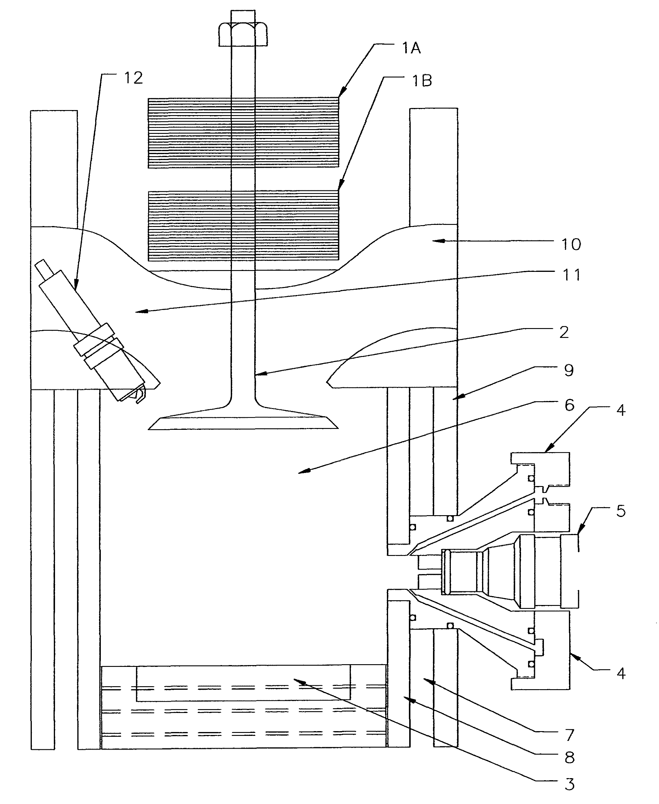
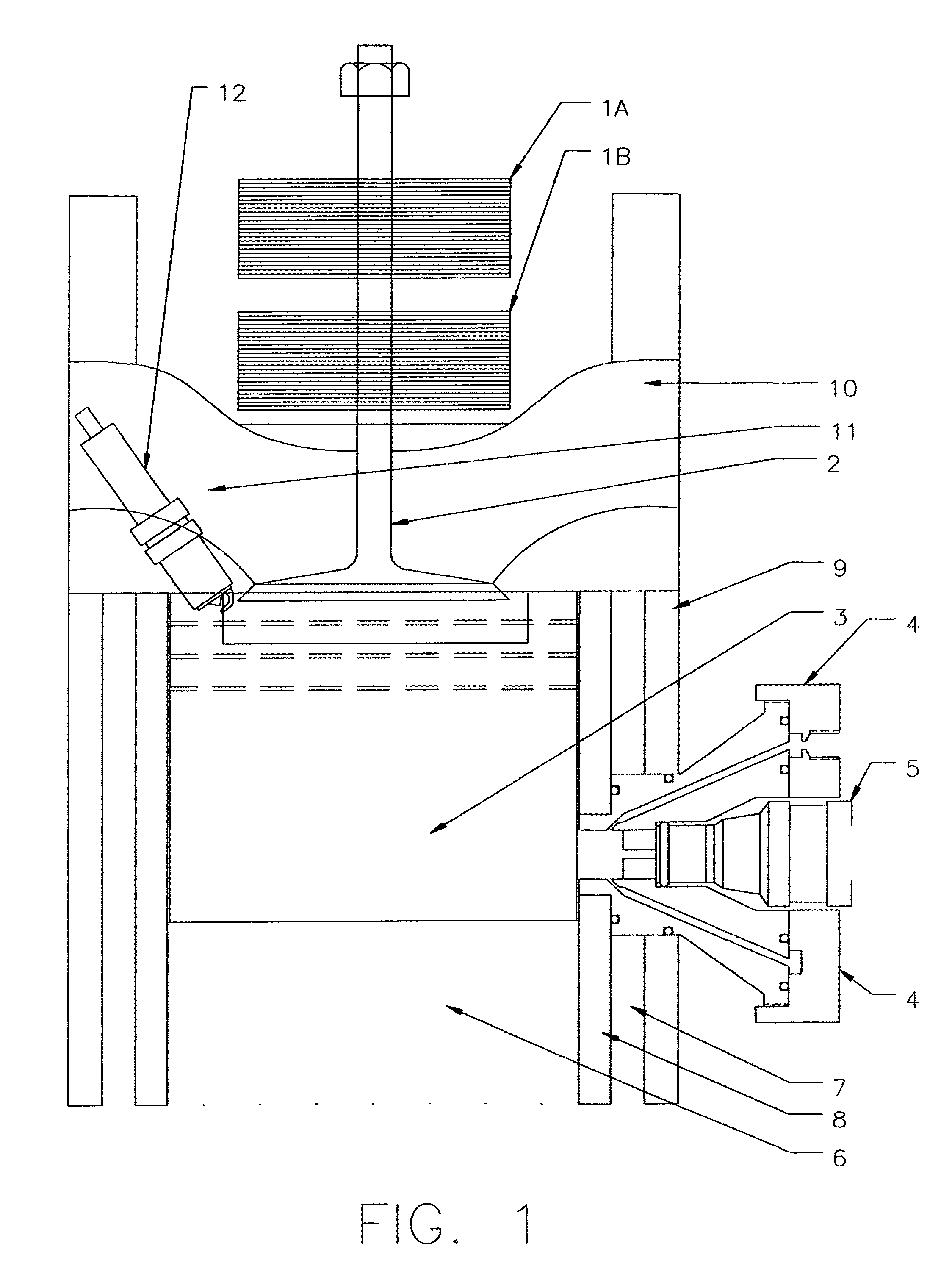
[0018]Referring now to the drawings and to FIG. 1 there of in particular showing the principal of a new concept of an internal combustible engine.

[0019]FIG. 1 shows the use of an Electric Magnetic Solenoid 1A and 1B, to operate the poppet valve 2 of this engine. It will replace the use of the camshaft, push rods, valve springs, timing gears and timing chain. Eliminating these parts will improve the performance of the engine. FIG. 1 shows the Electric Magnetic Solenoid 1A retracting a single poppet valve 2 to a closed position. Using the Electric Magnetic Solenoid 1A and 1B will eliminate the duration lag time of the conventional camshaft lobe. The Electric Magnetic Solenoid 1A gives instant full opening position and 1B gives instant full closed position of the poppet valve 2. This action gives longer and better breathing time for the intake and exhaust strokes of the engine.

[0020]FIG. 1 shows the piston 3 at top dead center (TDC). This Fig. shows the piston 3 at the end of the compr...


PUM


Abstract

The invention presents new and useful improvements in the mechanical design of control elements of a reciprocating piston engine. The camshaft is replaced by electric magnetic solenoids that operate a single poppet valve for each cylinder. The invention also includes an air injector combined with a fuel injector, mounted through the engine block and into the cylinder. The injectors are located in the lower ⅓ of the piston stroke area of said cylinder. The ability of the air injector to force air into the cylinder while the poppet valve is open will clean the cylinder of all exhaust gases. With the poppet valve closed the air and fuel injectors can inject any amount of air fuel mixture that is desired into the cylinder, resulting in the possibility of a power boost equal to that of a supercharged engine.

Description

BACKGROUND OF THE INVENTION[0001]The invention relates to the intake of air and fuel mixture process of a piston driven internal combustion engine which operate on either the two stroke principle or the four stroke principle. In particular, the invention provides an unique way to improve performance and economy of piston driven internal combustion engine. In the design of most standard engines, two valves are employed in the cylinder head to control the unidirectional flow through their corresponding parts and are thus able to regulate the flow of air charge to the engine cylinder and flow of combustion gas from the engine cylinder. The newer high performance engines in use today's automobiles now contain as many as four such poppet valves per cylinder. This has been done primarily to improve volumetric efficiency. However on the intake stroke of the engine, the piston still has to draw fuel from the intake manifold into the cylinder through the intake valve opening of the engine. A...

Claims


Application Information

Patent Timeline
IPC IPC(8): F02M23/04
CPCF01L9/04F02B23/104F02B25/02F02M67/02F02M69/045F01L2009/0407F02B2075/025F02B2075/027F02B2075/125F02M2023/008Y02T10/125Y02T10/123Y02T10/12F01L2009/2107F01L9/20
Inventor NICK, DONALD O.
Owner DONICK ENGINES
Why Eureka
Try Eureka