Jet dispenser comprising magnetostrictive actuator

a technology of magnetostrictive actuator and dispenser, which is applied in the direction of liquid transfer device, soldering device, light and heating apparatus, etc., can solve the problems of insufficient fluid outlet velocity for dispense of high-viscosity fluid, adversely affecting the ability of the delivery system to dispense precise, quantitative amounts of fluid material, etc., to achieve the effect of larger strokes and higher efficiency

Active Publication Date: 2011-11-15
ASM ASSEMBLY AUTOMATION LTD
View PDF22 Cites 12 Cited by
  • Summary
  • Abstract
  • Description
  • Claims
  • Application Information

AI Technical Summary

Benefits of technology

[0013]It is thus an object of this invention to provide a jet dispensing system for dispensing highly viscous fluids which allows a dispensing piston to achieve higher efficiency and larger strokes as compared to at least some of the aforesaid prior art.

Problems solved by technology

A disadvantage of using a syringe dispenser is the problem of stringing or sticking of a bead of the fluid material to a nozzle, which adversely affects the ability of the delivery system to dispense precise, quantitative amounts of fluid material.
This technology is limited primarily to fluids with low viscosity.
Rapid dispensing can be achieved using such magnetostrictive actuators, but as the piston stroke is limited by the low strain of the giant magnetostrictive material, the outlet velocity of fluid is not high enough to dispense highly viscous fluid.
Nevertheless, this dispenser cannot dispense highly viscous fluid.
Furthermore, the working distance between a nozzle and a substrate has to be less than 0.5 mm, which limits flexibility.
Furthermore, when the piston hits the nozzle seat, the impact may damage the structure and a loud noise is also produced.
Likewise, jet dispensers actuated by electric solenoids have the same problems as dispensers actuated by air solenoids.

Method used


Image

  • Jet dispenser comprising magnetostrictive actuator
  • Jet dispenser comprising magnetostrictive actuator
  • Jet dispenser comprising magnetostrictive actuator

Examples


Embodiment Construction

[0025]The preferred embodiment of the present invention will be described hereinafter with reference to the accompanying drawings.

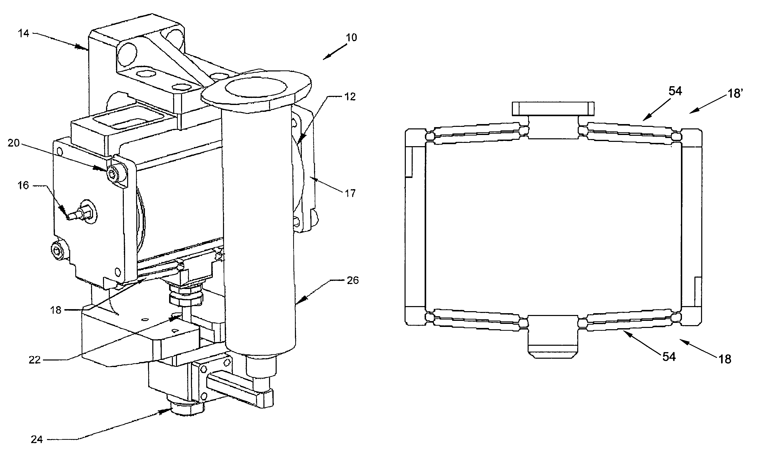
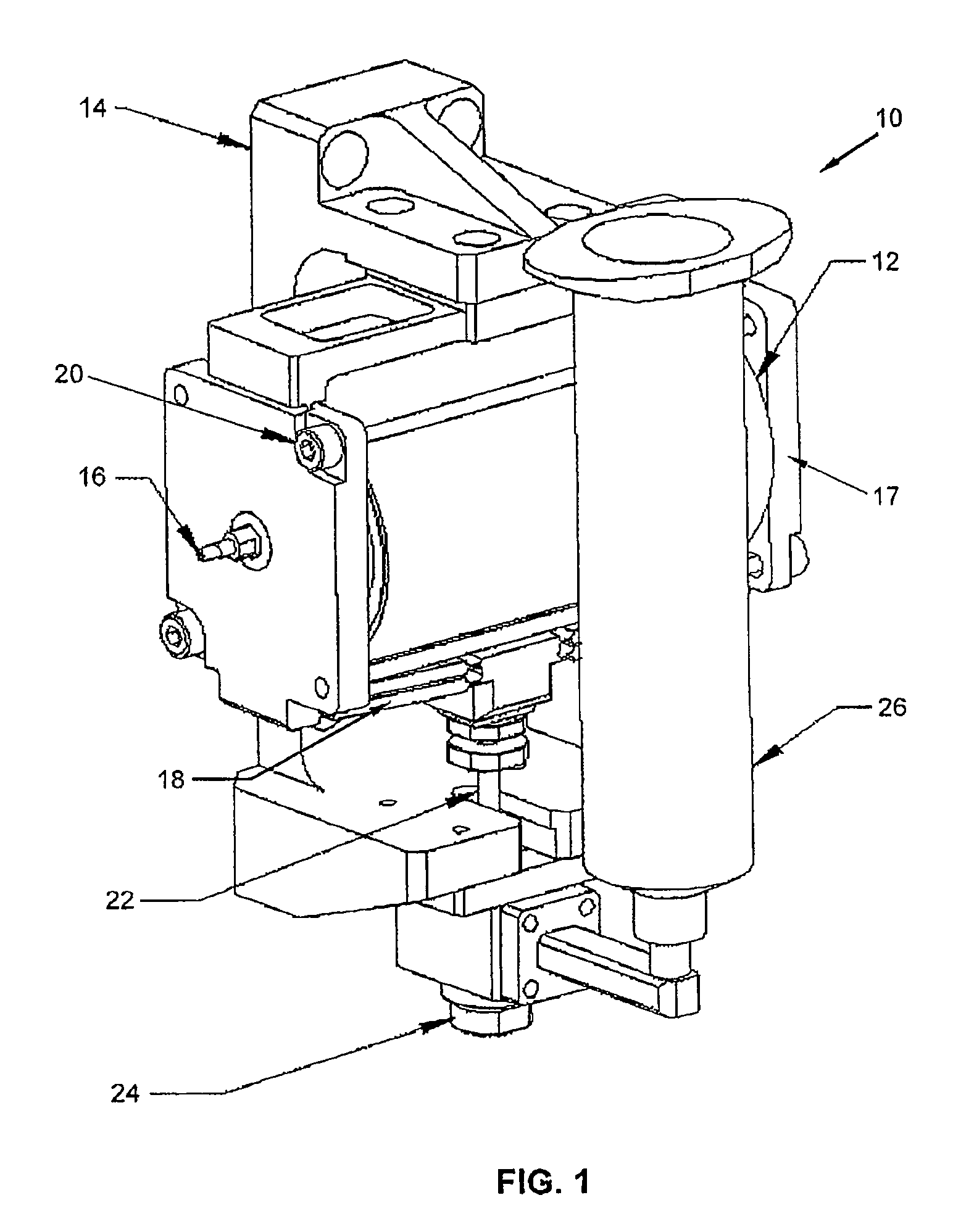
[0026]FIG. 1 is an isometric view of a jet dispenser 10 incorporating a giant magnetostrictive actuator 12 according to the preferred embodiment of the invention. A first set of flexural elements in the form of a flexural amplifier 18 is coupled to first and second ends of the actuator 12. A jet dispenser bracket 14 supporting the actuator 12 is coupled to the actuator 12 via a second set of flexural elements in the form of another flexural amplifier 18′ that is coupled to the said first and second ends of the actuator 12. The first and second sets of flexural amplifiers 18, 18′ are preferably located on opposite sides of the actuator 12. The jet dispenser 10 further includes a fluid supply 26 located next to the actuator 12. The giant magnetostrictive actuator 12 is responsive to electric currents to expand or contract. The expansion or contraction of th...


PUM


Abstract

A jet dispenser is provided with a giant magnetostrictive actuator which expands or contracts in response to electric currents. A set of flexural elements is coupled to first and second ends of the giant magnetostrictive actuator and flexes when the giant magnetostrictive actuator expands or contracts. The jet dispenser further comprises a chamber containing fluid and the fluid is dispensable through a nozzle which is in communication with the chamber. A piston coupled to the set of flexural elements is slidably located in the chamber and is actuable by flexion of the flexural elements to apply a force against the fluid for dispensing fluid through the nozzle.

Description

FIELD OF THE INVENTION[0001]The present invention relates to a jet dispenser for dispensing fluid material, and in particular, to dispensing fluids having high viscosity.BACKGROUND AND PRIOR ART[0002]In the semiconductor industry, dispensing systems are commonly used for dispensing finite volumes of fluid material. Dispensing systems are deployed in applications such as underfill, encapsulation, supplying adhesives and die attachment.[0003]One conventional method of dispensing uses syringe dispensers which apply time pressure dispensing or dispensing using volumetric valves. A disadvantage of using a syringe dispenser is the problem of stringing or sticking of a bead of the fluid material to a nozzle, which adversely affects the ability of the delivery system to dispense precise, quantitative amounts of fluid material. Stringing is likely to occur at lower pressures, such as when the pressure in the syringe is ramping up or ramping down. For the same reason, stringing also occurs fr...

Claims


Application Information

Patent Timeline
Patent Type & Authority Patents(United States)
IPC IPC(8): B05B1/08
CPCB23K3/0638H01L21/67005H01L21/6715B23K2201/40H01L21/67051B23K2101/40
Inventor XU, WENBIN
Owner ASM ASSEMBLY AUTOMATION LTD
Why Eureka
Try Eureka