Method and device for measuring soil parameters by means of compaction machines

a technology of soil compaction machine and measurement method, which is applied in the direction of in situ soil foundation, gravity wave measurement, reradiation, etc., can solve the problems of inconvenient use of conventional measurement methods and devices, limited number of measurements on a given surface, and inability to meet other soil compaction devices

Inactive Publication Date: 2011-11-15
WACKER NEUSON SE
View PDF8 Cites 11 Cited by
  • Summary
  • Abstract
  • Description
  • Claims
  • Application Information

AI Technical Summary

Benefits of technology

[0064]Due to the eccentric force application point, the contact element experiences an additional rotational acceleration that counteracts the mass inertia of the contact element.

Problems solved by technology

Conventional measurement methods and devices separate from the compaction devices require a significant additional expense, because in addition to the compaction device measurement devices must also be made available, which generally require a correspondingly trained operator.
Moreover, the number of measurements on a given surface is limited by time constraints; i.e., only some spot samples can be measured.
In contrast, the known measurement methods and devices are not suitable for other soil compaction devices, in particular vibrating plates or tampers.
Even if the roller tires jump off the soil, these airborne phases are relatively short, so that the influence of the error is low.
In contrast, in the case of tampers and vibrating plates long airborne phases and short contact times must be assumed, so that the measurement methods known from the prior art, which are geared toward a periodic movement characteristic, are not suitable.
In addition, the soil contact elements of vibrating plates and tampers are subject to a rather chaotic movement characteristic, because they constantly have to absorb soil forces at different places due to the jumping or airborne phases.

Method used


Image

  • Method and device for measuring soil parameters by means of compaction machines
  • Method and device for measuring soil parameters by means of compaction machines
  • Method and device for measuring soil parameters by means of compaction machines

Examples


Embodiment Construction

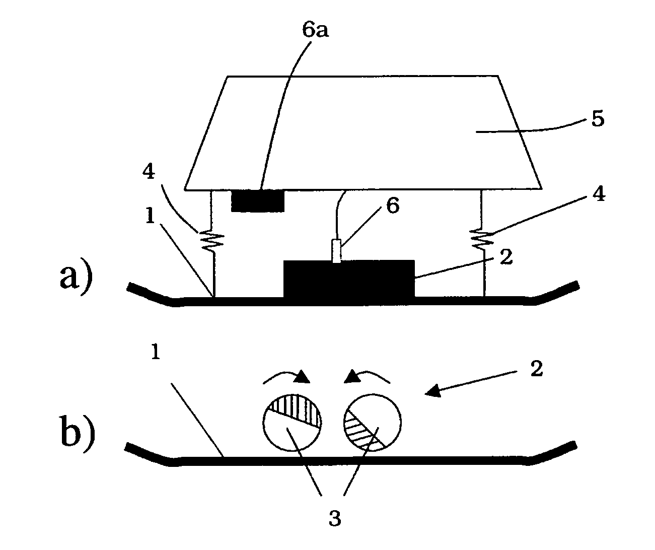
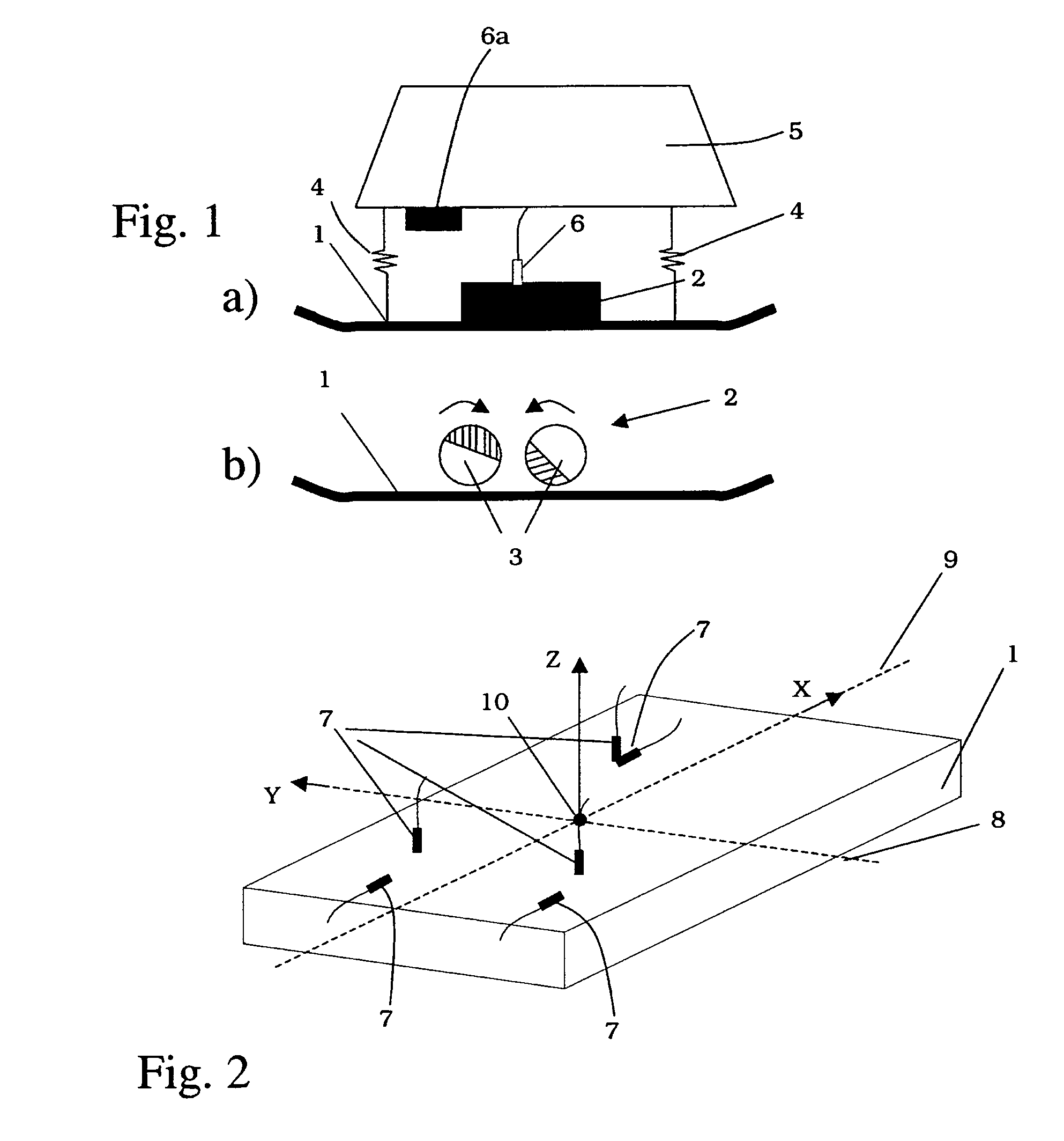
[0098]FIG. 1 shows, in a highly simplified schematic representation, a vibrating plate acting as a soil compaction device, having a contact element 1. Contact element 1 can also be, in a similar manner, a component of a vibrating tamper. The contact element, acting as a soil contact plate in this way, transfers, in a known manner, vibration forces produced by a vibration exciter 2 into the soil being compacted.

[0099]As is shown in FIG. 1b), vibration exciter 2 can be made up, in a known manner, of two imbalance shafts 3 that are capable of rotation in mutually opposite directions, and whose phase position to one another can be adjusted in order to achieve steerability, or change of direction, of the soil compaction device during traveling operation.

[0100]Contact element 1 is connected via a spring device 4 to an upper mass 5 so as to be capable of motion. A drive for vibration exciter 2 is standardly housed in upper mass 5. Moreover, FIG. 1a) shows a measurement sensor 6 that can be...


PUM

PropertyMeasurementUnit
contact forceaaaaaaaaaa
dynamic modulusaaaaaaaaaa
contact surface parameteraaaaaaaaaa

Abstract

A soil compaction device has a vibrated contact element that makes contact with the soil during a contact phase and that is exposed to a contact force exerted by the soil and travels over a contact distance. A dynamic stiffness of the soil is formed from the gradient of the contact force and from the contact distance. Furthermore, a contact surface parameter to take account of the actual contact surface of the contact element with the soil is determined. The dynamic deformation modulus is then the product of the contact surface parameter and the dynamic stiffness. The method allows the determination of the dynamic deformation modulus, and hence of the soil stiffness, during the compaction operation.

Description

BACKGROUND OF THE INVENTION[0001]1. Field of the Invention[0002]The present invention relates to a method for determining a soil parameter using a soil compaction device that has a contact element that is charged with vibration for soil compaction.[0003]2. Description of the Related Art[0004]Vibrating plates and vibrating tampers, as well as vibrating rollers, are known for use as soil compaction devices. Each of these has at least one soil contact element that is charged with vibration by a vibration exciter and that introduces the vibration into the soil in order to achieve a compaction effect.[0005]In order to monitor the quality of compaction work, it is helpful to determine particular soil parameters, such as for example soil rigidity, deformability, load capacity, etc.[0006]In order to determine soil parameters, methods and devices are known that operate separately from soil compaction devices. Thus, there is a standardized plate load method (DIN 18134) in which a modulus of d...

Claims


Application Information

Patent Timeline
Patent Type & Authority Patents(United States)
IPC IPC(8): G01N3/00E01C19/38
CPCE01C19/288E01C19/38E02D3/074E02D1/022
Inventor STENZEL, OTTO W.WAGNER, STEFANLANGE, DITTMAR
Owner WACKER NEUSON SE
Why Eureka
Try Eureka