Miniature high-voltage power supplies

a high-voltage power supply, miniature technology, applied in the direction of instruments, process and machine control, television systems, etc., can solve the problems of affecting the efficiency of modulating the voltage across the capacitive device, prohibitive use of such large/heavy power components, and large relative weight of power components, so as to minimize switching losses and minimize power dissipation

Active Publication Date: 2011-11-15
SRI INTERNATIONAL +1
View PDF5 Cites 23 Cited by
  • Summary
  • Abstract
  • Description
  • Claims
  • Application Information

AI Technical Summary

Benefits of technology

[0012]The present invention includes novel circuitry for powering devices requiring a high-voltage supply. The power circuitry of the present invention provides a novel circuit topology which utilizes extremely small and light-weight components which enable an ultra-miniature power supply architecture and which also minimize power dissipation due to switching losses. In particular, the novel power topology comprises high-resistance switching components. This is opposite to the approach taken with most power circuits of the prior art which employ low-resistance switches in order to minimize switching losses. Additionally, the switching components of the inventive circuitry are designed to operate at frequencies which are much lower than prior art power circuits without compromising the size of the circuit's magnetic components, i.e., inductor / transformer. This novel circuitry provides some unpredictable advantages which are explained in greater detail below.
[0014]The present invention also provides power supplies comprising the subject power circuitry where the components thereof are relatively small and arranged in such a manner to reduce the number and size of the necessary components, thus reducing the overall space requirements and total cost of the power supply. Moreover, the subject power circuit topology provides a manufacturer with the flexibility of scaling the size of the power supply to the desired voltage output of the supply. More specifically, the subject topology allows sealing of the power supply size as power output requirements are lowered.

Problems solved by technology

Components, such as the transformer or inductor, diodes, and capacitors used in high-voltage power supply circuits must be able to withstand the effects of high voltages and, thus, are often relatively large and heavy.
In smaller and / or portable devices necessitating the use of a low DC voltage source, i.e., a battery supplying 5V or less, use of such large / heavy power components is prohibitive.
Even where power supply size is not as much of an issue, where the high-voltage device being powered is mostly capacitive in nature, efficiently modulating the voltage across the capacitive device can be problematic.
However, a significant number of parts must be added (as many as ten or more cascaded switch multipliers may be required) in addition to the main power devices, possibly including high voltage drive transformers with difficult isolation requirements.
In a fast switching circuit, this energy is dissipated in the transistor switch at every turn-on, and can result in a substantial amount of power dissipation.
Power dissipation is particularly acute in high voltage circuits where losses due to high-frequency switching activity (commonly referred to as “switching loss”) can quickly reach unacceptable levels.
In addition to reducing efficiency, these losses can increase the temperature of the switching elements beyond their ratings, causing premature failure.
Converter topologies such as zero voltage switching (ZVS) and zero current switching (ZCS) address the problem of power dissipation due to switching loss; however, they have complex designs with a high part count, which adds to the size and cost of the power supply.
They are advantageous in that they are relatively small and compact; however, conventional boost converters do not fully address the problem of power dissipation due to switching losses.
Additionally, because they employ high-impedance switching circuits, they are also subject to conduction losses.
This increases the size and cost of the power supply.
Even where the high-voltage device being powered requires a relatively low supply voltage, i.e., less than about 2 kV, the components of conventional boost converters do not allow for much of a corresponding reduction in power supply size due to the additional circuitry required to mitigate the conductive losses.
While these circuit topologies reduce power dissipation and are not prohibitively large or heavy for use with smaller high-voltage devices, they are still too large and heavy to be provided in a form fit to accommodate miniature device applications, such as cell phone camera modules, camera flashes, etc.
However, the size of the required transformer increases as the frequency of the charge / discharge cycle decreases.
Thus, for the majority of applications in which weight, size and mass considerations are essential, the required transformer is unacceptably large.
Of course, this approach presents the problem of power dissipation due to switching losses discussed above.
While the sizes of these “miniature” power supplies are relatively small, the inventors hereof are not aware of an available power supply having an even smaller architecture, or one that could be scaled-down in size even with a substantially lower output voltage requirement, e.g., less than 2 kV.
In sum, prior art high-voltage power supply technology involves a tradeoff between size / weight and power dissipation due to switching losses.

Method used


Image

  • Miniature high-voltage power supplies
  • Miniature high-voltage power supplies
  • Miniature high-voltage power supplies

Examples


Embodiment Construction

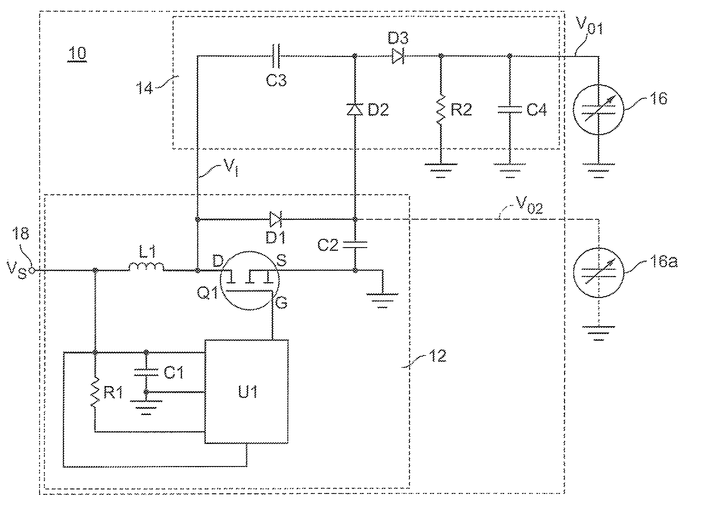
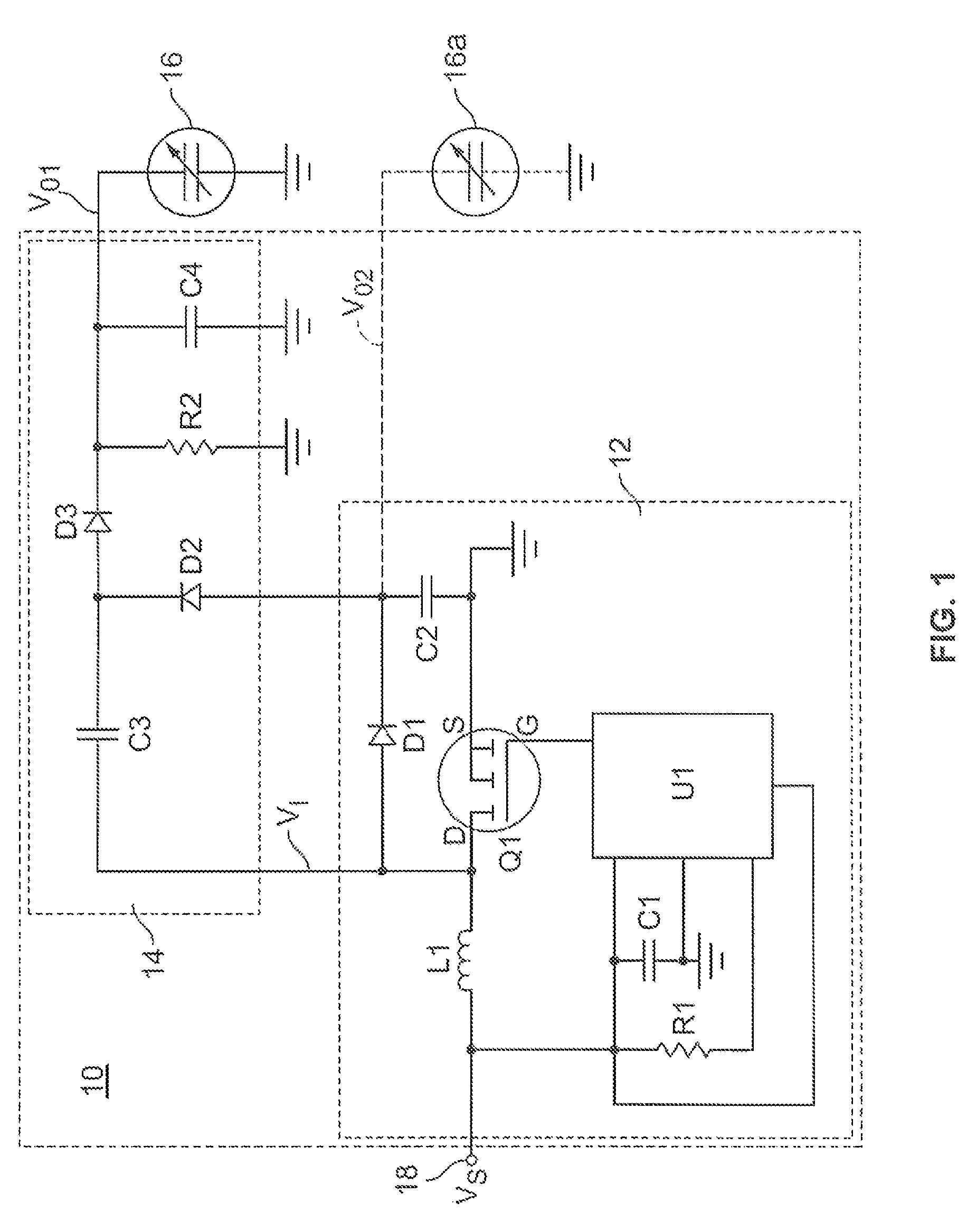
[0023]The present invention provides power circuitry and power supplies for use in powering high-voltage devices where the available input voltage is relatively low and is required to be “stepped up” to a relatively high voltage to adequately power the device. While the subject invention may be employed with any high-voltage device, the invention is particularly described in the context of a device which provides a capacitive load. Still yet, for purposes of illustration only, the capacitive load used in the context of this description is a dielectric elastomer / electroactive polymer transducer, which is described in greater detail below.

[0024]A general configuration of a power supply 10 of the present invention is provided in the block diagram of FIG. 1. In general, power supply 10 includes power circuit 12 and voltage multiplier circuit 14. Power circuit 12 has an input 18 coupled to a relatively low DC source signal VS (e.g., 2 to 5 volt range) and an output coupled to the input s...


PUM


Abstract

The present invention provides a system comprising a high-voltage capacitive device and a power circuit electrically coupled to the capacitive device, wherein the power circuit is configured for stepping up a lower DC source voltage to a higher DC output voltage, wherein the source voltage is less than about 5 V, and wherein the output voltage is at least about 1.25 kV, and wherein the power circuit comprises a magnetic component and a switching component for charging and discharging the magnetic component, wherein the switching component has a high resistance of at least about 5 ohms.

Description

FIELD OF THE INVENTION[0001]The present invention is related to very compact, low-power, high-voltage power supplies.BACKGROUND[0002]High-voltage power supplies are commonly used and well-known for powering devices which require a high DC voltage. Most high-voltage power supplies include a transformer or inductor for converting or stepping-up a relatively low DC source voltage to a relatively high DC output voltage. Components, such as the transformer or inductor, diodes, and capacitors used in high-voltage power supply circuits must be able to withstand the effects of high voltages and, thus, are often relatively large and heavy. In smaller and / or portable devices necessitating the use of a low DC voltage source, i.e., a battery supplying 5V or less, use of such large / heavy power components is prohibitive. Even where power supply size is not as much of an issue, where the high-voltage device being powered is mostly capacitive in nature, efficiently modulating the voltage across the...

Claims


Application Information

Patent Timeline
Patent Type & Authority Patents(United States)
IPC IPC(8): G05F1/40
CPCH04N5/2257H02M3/156H04N23/57H10N30/802
Inventor PELRINE, RONALD EDWARDPOLYAKOV, ILYA
Owner SRI INTERNATIONAL
Why Eureka
Try Eureka