Directional antenna and portable electronic device using the same

a portable electronic device and antenna technology, applied in the direction of antennas, antenna details, elongated active element feeds, etc., can solve problems such as difficulties in the prior art, and achieve the effect of optimal signal transmission

Active Publication Date: 2011-11-15
FIH (HONG KONG) LTD
View PDF6 Cites 4 Cited by
  • Summary
  • Abstract
  • Description
  • Claims
  • Application Information

AI Technical Summary

Benefits of technology

[0008]It is an object of the present invention to provide a directional antenna which is implemented in an electronic device and properly adjusted toward a direction to achieve optimal performance. In addition, the directional antenna is adjusted or tuned toward a predetermined direction responsive to position of the electronic device to achieve optimal performance of signal transmission and receiving.
[0015]According to the present invention, the directional antennal for signal transmission over a long distance and the portable electronic device utilizing the directional antenna use L-shaped structure to achieve ideal performance of signal transmission over a long distance. In addition, with the gravity sensor, the processor and the switches, the directional antenna is automatically adjusted to a predetermined direction even though orientation of the electronic device is changed at any time. Thus, the optimal signal transmission is achieved.

Problems solved by technology

In addition, the directional antenna of GPS must be continuously directed toward the satellite so it is difficult in the prior art.

Method used


Image

  • Directional antenna and portable electronic device using the same
  • Directional antenna and portable electronic device using the same
  • Directional antenna and portable electronic device using the same

Examples


Embodiment Construction

[0023]The following detailed description is of the best presently contemplated modes of carrying out the invention. This description is not to be taken in a limiting sense, but is made merely for the purpose of illustrating general principles of embodiments of the invention. The scope of the invention is best defined by the appended claims.

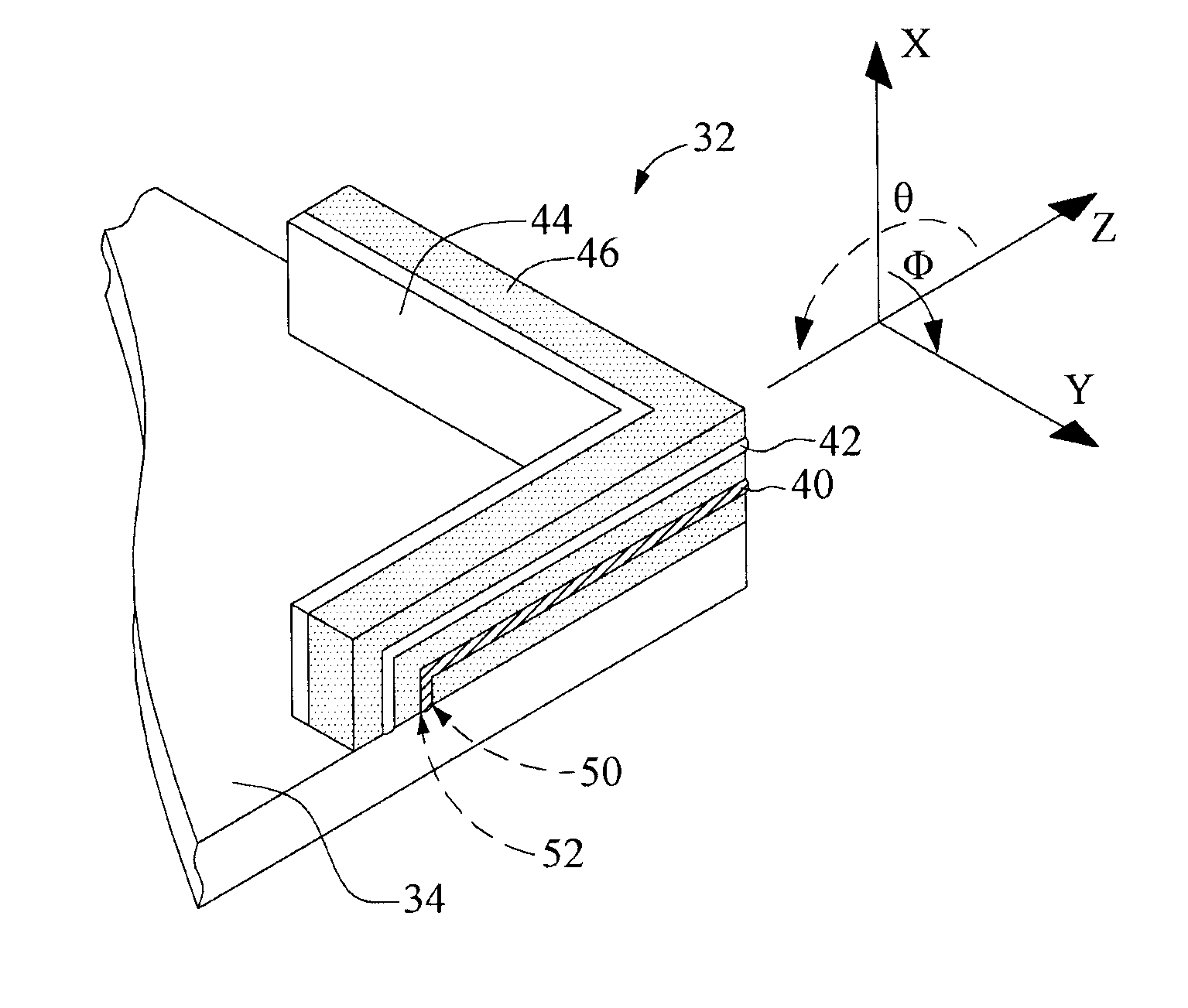
[0024]Referring to FIG. 1, FIG. 1 illustrates a perspective view of a directional antenna 32 positioned at a substrate 34. According to the present invention, the directional antenna 32 is positioned at the substrate 34 and implemented in an electronic device 30. It is preferred that the directional antenna 32 is positioned at corners of the substrate 34.

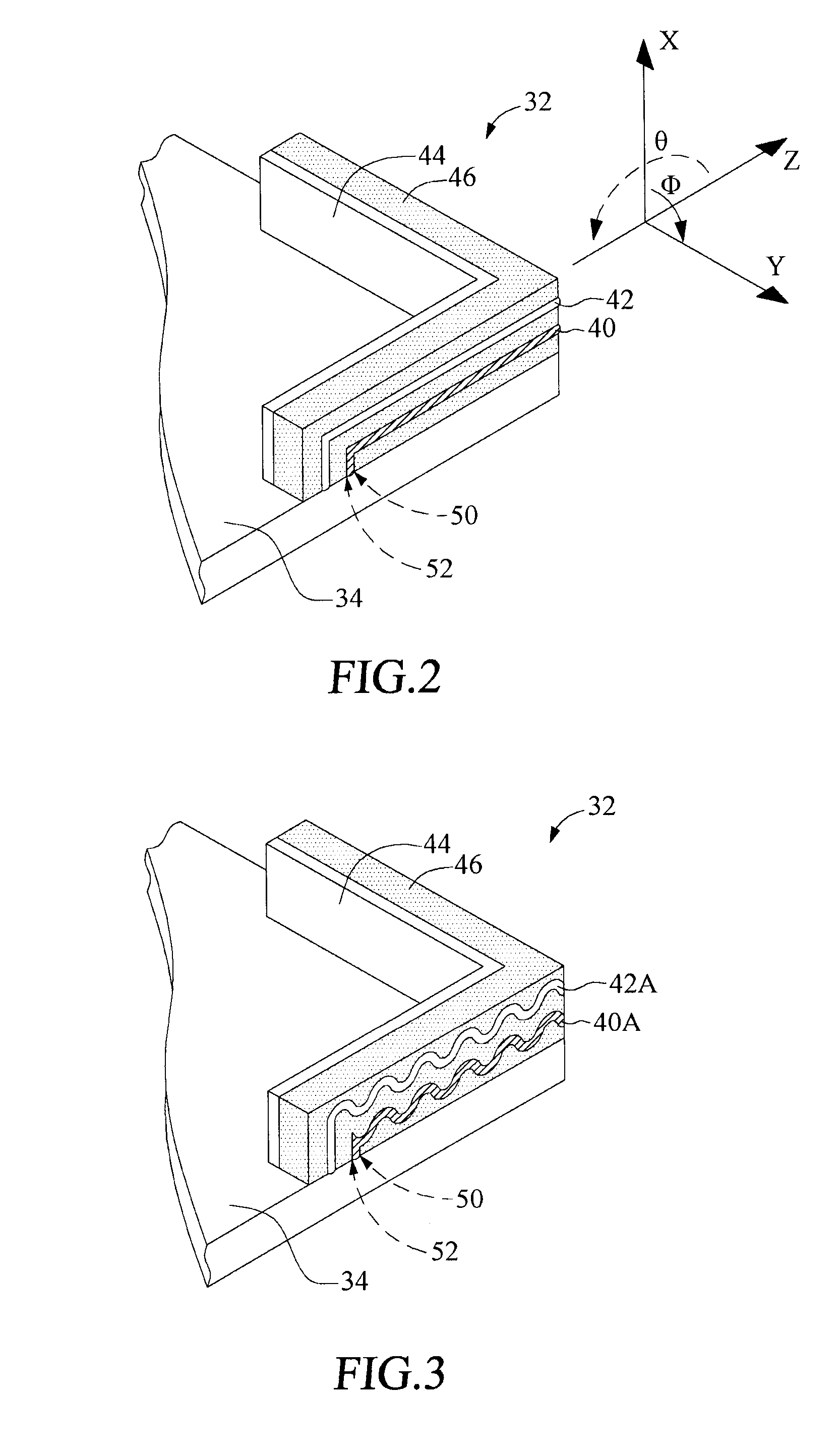
[0025]Refer to FIG. 2. FIG. 2 illustrates a perspective view of the directional antenna 32. The directional antenna 32 includes at least one L-shaped radiator 40, at least one L-shaped oscillator 42, and at least one L-shaped reflector 44.

[0026]The L-shaped radiator 40 is substantially a fold line...


PUM


Abstract

A directional antenna and a portable electronic device using the same are provided. The directional antenna includes L-shaped radiator, L-shaped oscillator, and L-shaped reflector and it is preferred that the directional antenna is positioned at corners of the substrate. The L-shaped radiator is made resonant by the L-shaped oscillator and has higher gain to maximize performance of signal transmission. The directional antenna achieves signal transmission in a specific direction over a long distance by the L-shaped reflector. In addition, with the gravity sensor, the processor and the switches, the directional antenna is automatically adjusted to a predetermined direction to transmit and receive signals even through orientation of the electronic device is changing at any time.

Description

BACKGROUND OF THE INVENTION[0001]1. Field of the Invention[0002]The present invention relates to a directional antenna, and in particular to a directional antenna which is implemented in electronic devices.[0003]2. Description of Related Art[0004]Directional antennas are usually implemented in electronic devices or adapted in the electronic devices, and they can transmit or receive electromagnetic waves in a predetermined direction. After electrical signals of the electronic devices are converted into electromagnetic waves, the electromagnetic waves are transmitted through the directional antennas. In addition, the electromagnetic waves are received through the directional antennas, and then converted into electrical signals for electronic devices. Because the directional antennas transmit or receive electromagnetic waves much more in one direction than other directions, the directional antennas are suitable for signal transmission over a long distance. In this light, the directiona...

Claims


Application Information

Patent Timeline
Patent Type & Authority Patents(United States)
IPC IPC(8): H01Q19/00H01Q3/24
CPCH01Q1/243H01Q3/24H01Q9/42H01Q19/106H01Q21/28
Inventor MA, CHIN-HUNGTSAI, SHIH-LIANG
Owner FIH (HONG KONG) LTD
Why Eureka
Try Eureka