Cooling system for the cooling of heat-producing devices in an aircraft

a cooling system and heat-producing device technology, which is applied in the direction of domestic cooling apparatus, lighting and heating apparatus, energy-efficient board measures, etc., can solve the problems of undesirable heating of the interior of the aircraft, large structural space of individual systems, and little flexibility

Active Publication Date: 2011-11-22
AIRBUS OPERATIONS GMBH
View PDF11 Cites 0 Cited by
  • Summary
  • Abstract
  • Description
  • Claims
  • Application Information

AI Technical Summary

Benefits of technology

[0019]In one variation of the invention, the cold carrier medium can flow through both a cooling machine which is turned off and a cooling machine which is turned on. In this way, the mix temperature of the cold carrier medium in the preliminary run supply can be raised.
[0020...

Problems solved by technology

The provision of this type of individual systems requires relatively large amounts of structural space within the aircraft and there is little flexibility.
However, this leads to undesirable heating up of the interior of the aircraft.
The disadvantage, however, of this state of the art technology is that each cooling chamber requires a separate cold air chamber.
This means that the ...

Method used


Image

  • Cooling system for the cooling of heat-producing devices in an aircraft
  • Cooling system for the cooling of heat-producing devices in an aircraft
  • Cooling system for the cooling of heat-producing devices in an aircraft

Examples


Embodiment Construction

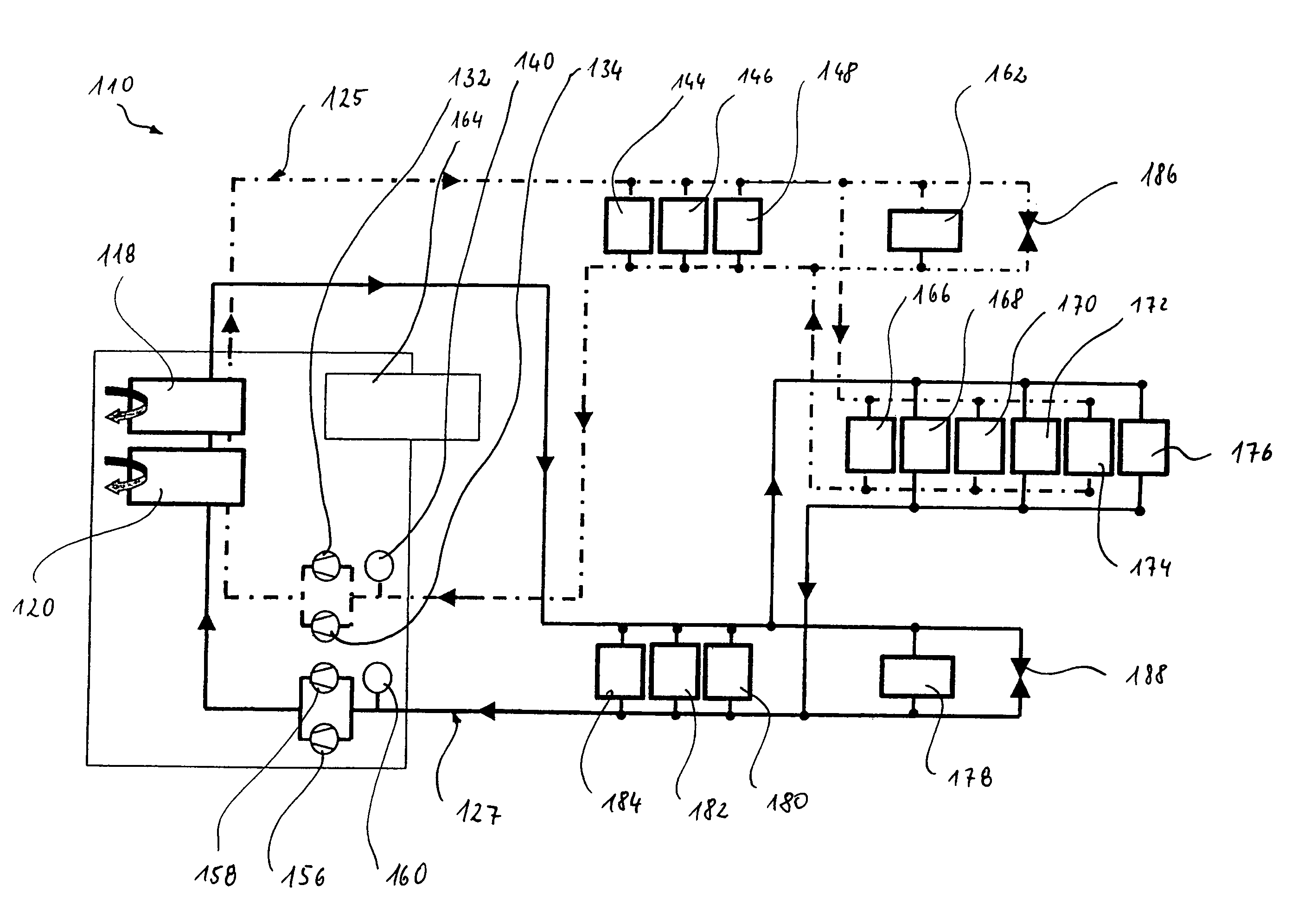
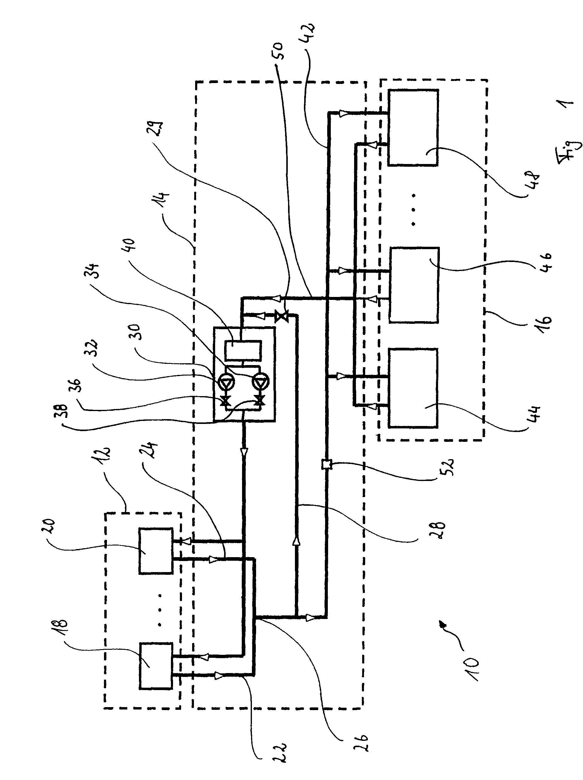
[0027]In the attached FIG. 1, a cooling system in accordance with the invention is shown is by 10. This includes a cold producing device 12, a cold conveyance system 14 and an area 16, in which cold is consumed.

[0028]The cold producing device 12 has two cooling machines 18 and 20, in which a cold carrier medium is cooled down by means of a cold vapour process generally known in the field of thermodynamics, and supplied to the cold conveyance system 14 along two parallel lines 22 and 24 of a cooling circuit 25. In the cold conveyance system 14, the two parallel lines 22 and 24 are united at a point 26. Cold carrier medium is supplied to a pump unit 30 by means of a supply line 28 provided with a specially controllable check valve 29. The pump unit 30 has two pumps 32 and 34 which are controlled parallel to one another, and to which separately controllable check valves 36 and 38 are assigned. A cold carrier medium intermediary storage unit 40 is connected to the parallel arrangement o...


PUM


Abstract

A cooling system for the cooling of heat producing devices in an aircraft is designed with a central cold producing device, at least one cold consumer and a cold conveyance system which connects the cold producing device and the cold consumer. With this cooling system, the cold conveyance system has at least one cooling circuit which supplies a cooled cold carrier medium from the cold producing device to at least one cold consumer and brings the cold carrier medium back to the cold producing device, so that at least one cold consumer is supplied with the cold produced in the cold producing device.

Description

[0001]This application claims the benefit of International Application No PCT / EP2004 / 014851, filed on Dec. 30, 2004, under 35 U.S.C. §371 and / or as a continuation under 35 U.S.C. §120, and German Application. No. 103 61 645.4, filed on Dec. 30, 2003.TECHNICAL FIELD[0002]This invention relates to a cooling system for the cooling of heat-producing devices in an aircraft.BACKGROUND[0003]In the interior of an aircraft, besides the aircraft's air-conditioning system there are a variety of different technical devices which produce heat and which, in order to guarantee safe function, must be cooled. For this reason, different cooling systems have been provided in aircrafts for a long time which are associated as individual solutions to the respective technical devices which are to be cooled. The provision of this type of individual systems requires relatively large amounts of structural space within the aircraft and there is little flexibility. Moreover, this type of individual systems oft...

Claims


Application Information

Patent Timeline
IPC IPC(8): B60H1/32B64D11/04B64D13/06F25D17/02
CPCB64D11/04B64D13/06F25D17/02B64D2013/0629Y02T50/56Y02T50/50
Inventor SCHERER, THOMASWITSCHKE, MATTHIASCOLBERG, CARSTEN
Owner AIRBUS OPERATIONS GMBH
Why Eureka
Try Eureka