Drilling fluid pump systems and methods

a pump system and fluid technology, applied in the direction of machines/engines, positive displacement liquid engines, borehole/well accessories, etc., can solve the problems of premature failure of seals, and achieve the effect of reducing the deflection (“breathing”) of the module wall near the seal surface of the valve cartridg

Active Publication Date: 2011-11-22
NAT OILWELL VARCO LP
View PDF25 Cites 3 Cited by
  • Summary
  • Abstract
  • Description
  • Claims
  • Application Information

AI Technical Summary

Benefits of technology

[0014]In certain embodiments of modules in systems according to the present invention, the modules are made of relatively expensive material, e.g. S165M stainless steel e.g. with a thickness of about 2.36″ (as has been done in the past with prior modules). In other aspects, modules according to the present invention are made with a relatively thicker wall thickness, e.g. at least 25% thicker, and, in certain aspects, 50% thicker, or more, e.g. also using relatively cheaper material, e.g. 8630M alloy steel. By using thicker-walled modules, deflection (“breathing”) of the module wall near seal surfaces of the valve cartridge is reduced. Such deflection is the result of fluctuating internal pressure due to pump operation and can cause the premature failure of seals.

Problems solved by technology

Such deflection is the result of fluctuating internal pressure due to pump operation and can cause the premature failure of seals.

Method used


Image

  • Drilling fluid pump systems and methods
  • Drilling fluid pump systems and methods
  • Drilling fluid pump systems and methods

Examples


Embodiment Construction

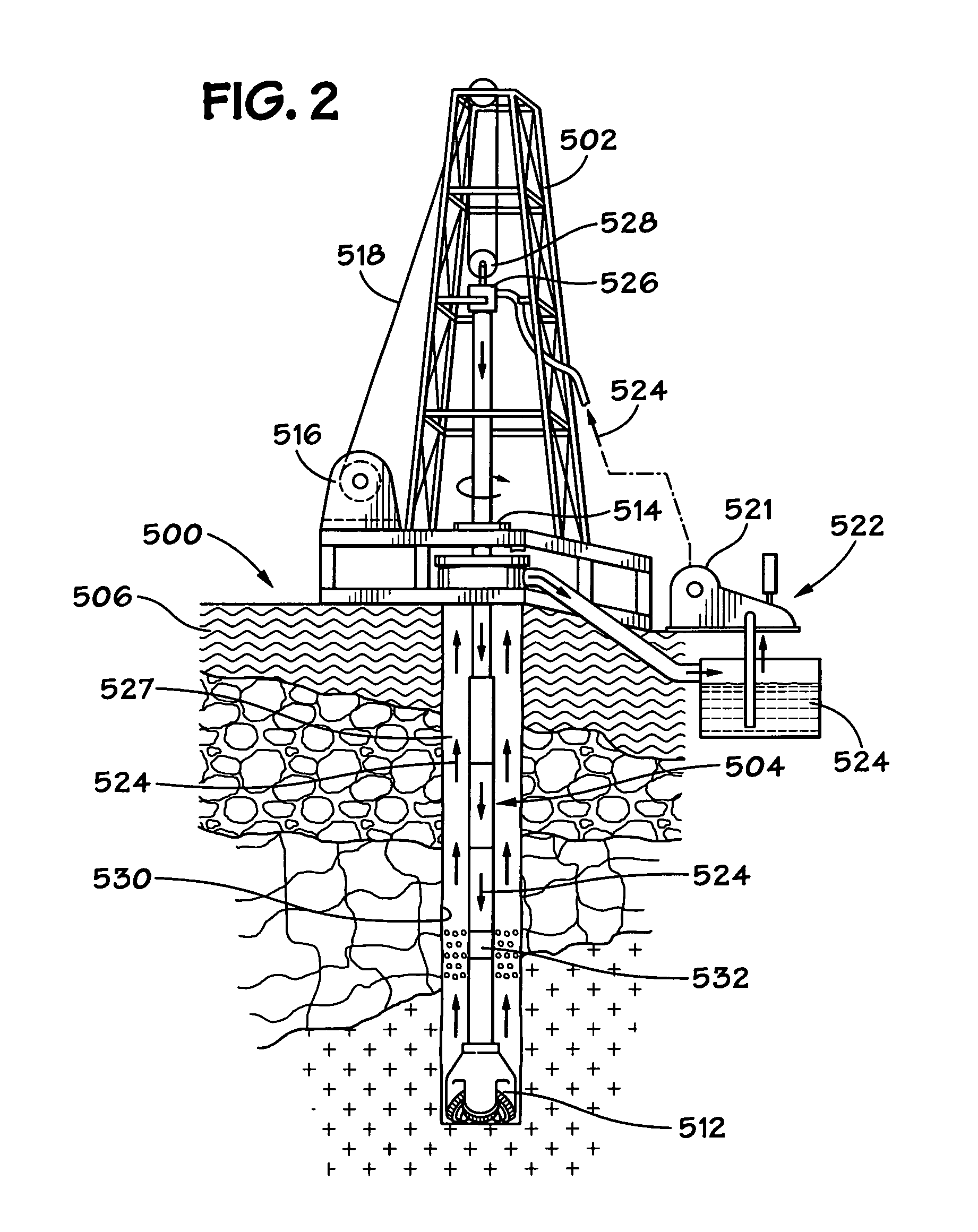
[0156]The system 500 shown in FIG. 2 includes a derrick 502 from which extends a drillstring 504 into the earth 506. The drillstring 504, as is well known, can include drill pipes and drill collars. A drill bit 512 is at the end of the drillstring. A rotary system 514, top drive system 526, and / or a downhole motor 532 (“fluid motor”, “mud motor”) may be used to rotate the drillstring 504 and the drill bit 512. A typical drawworks 516 has a cable or rope apparatus 518 for supporting items in the derrick 502. A system 522 with one, two, or more mud pump systems 521 according to the present invention supplies drilling fluid 524 to the drillstring 504. Drilling forms a wellbore 530 extending down into the earth 506.

[0157]During drilling, the drilling fluid 524 is pumped by pump(s) 521 of the system 522 into the drillstring 504 (thereby operating a downhole motor 532 if such an optional motor is used). Drilling fluid 524 flows to the drill bit 512, and then flows into the wellbore 530 th...


PUM


Abstract

A system for pumping fluid (e.g., but not limited to, drilling fluid), the system having pump apparatus; including a plurality of removable pump modules; and, in certain aspects, removable valve cartridges for such modules.

Description

BACKGROUND OF THE INVENTION[0001]1. Field of the Invention[0002]This present invention is directed to drilling wellbores in the earth, to systems for pumping drilling fluid (“mud”) for such operations, to pump modules for such systems, and methods of their use.[0003]2. Description of Related Art[0004]The prior art discloses a wide variety of drilling systems, apparatuses, and methods including, but not limited to, the disclosures in U.S. Pat. Nos. 6,944,547; 6,918,453; 6,802,378; 6,050,348; 5,465,799; 4,995,465; 4,854,397; and 3,658,138, all incorporated fully herein for all purposes. The prior art discloses a wide variety of drilling fluid pumps (“mud pumps”) used in drilling operations and pump systems; for example, and not by way of limitation, those pumps and systems disclosed in U.S. Pat. Nos. 6,257,354; 4,295,366; 4,527,959; 5,616,009; 4,242,057; 4,676,724; 5,823,093; 5,960,700; 5,059,101; 5,253,987; 6,718,955; and in U.S. application Ser. No. 10 / 833,921 filed Apr. 28, 2004 (a...

Claims


Application Information

Patent Timeline
Patent Type & Authority Patents(United States)
IPC IPC(8): E21B44/00
CPCE21B21/00F04B1/14F04B1/143F04B1/145E21B21/08
Inventor YATER, RONALD WILLIAMSEYFFERT, KENNETH WAYNETATE, JR., MAURICE
Owner NAT OILWELL VARCO LP
Why Eureka
Try Eureka