Transient signal encoding method and device, decoding method and device, and processing system

a transient signal and encoding technology, applied in the field of communication technologies, can solve the problems of unsatisfactory effect of transient signal recovery at the decoding end, and achieve the effect of improving the effect of transient signal recovery

Active Publication Date: 2011-11-22
CRYSTAL CLEAR CODEC LLC
View PDF33 Cites 28 Cited by
  • Summary
  • Abstract
  • Description
  • Claims
  • Application Information

AI Technical Summary

Benefits of technology

[0007]The present invention is directed to a transient signal encoding method and device, decoding method and device, and processing system, which are configured to improve the quality of recovery of transient signals.
[0014]According to the transient signal encoding method and device, decoding method and device, and processing system of the present invention, the time envelope is modified according to characteristics of the transient signal, such that the difference between the amplitude value of the time envelope having the maximal amplitude value and the amplitude values of the time envelopes of the other sub-frames before the sub-frame corresponding to the time envelope having the maximal amplitude value is more distinct, thereby improving the effect of recovery of the transient signal.

Problems solved by technology

In the prior art, the time envelope of the transient signal is not modified, and due to the influence of the processing in the signal encoding process, such as process by frame by frame, time-frequency transform, and frequency envelope, the transient signal is likely to generate a pre-echo; therefore, the prior art has the disadvantage that the effect of the transient signal recovered at the decoding end is not satisfactory.

Method used


Image

  • Transient signal encoding method and device, decoding method and device, and processing system
  • Transient signal encoding method and device, decoding method and device, and processing system
  • Transient signal encoding method and device, decoding method and device, and processing system

Examples


first embodiment

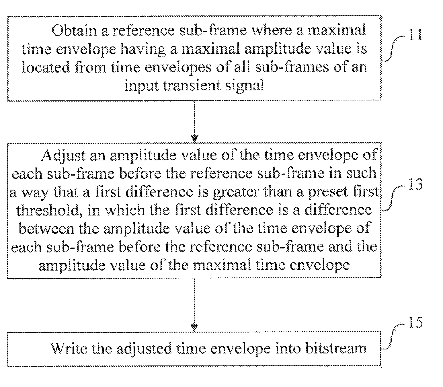
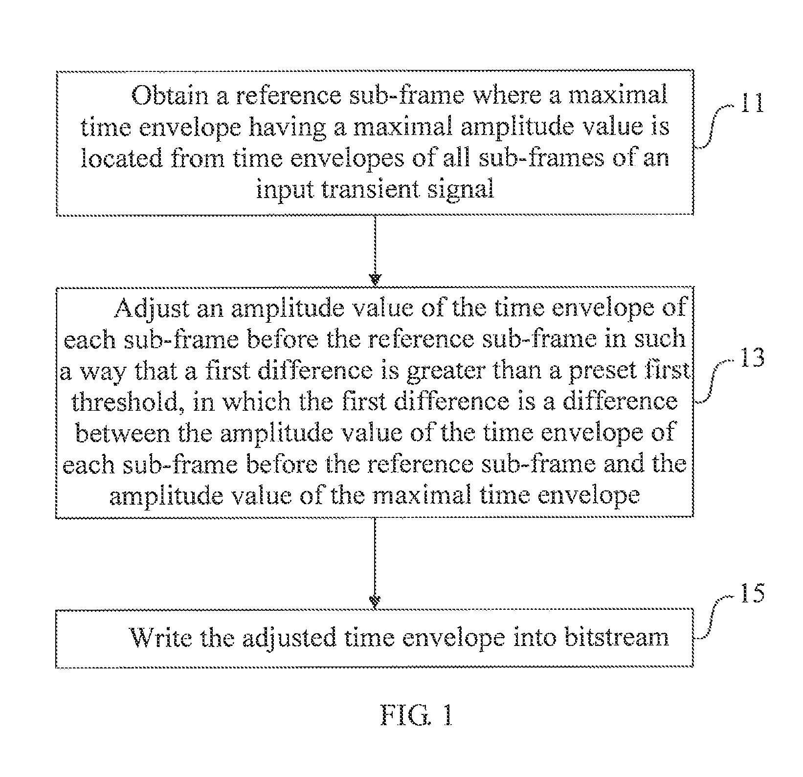
[0028]FIG. 1 is a flow chart of a transient signal encoding method according to the present invention. As shown in FIG. 1, the method includes the following steps.

[0029]In Step 11, a sub-frame where a time envelope having a maximal amplitude value (that is, a maximal time envelope) is located is obtained from time envelopes of all sub-frames of an input transient signal, in which the sub-frame is the reference sub-frame described in the embodiments of the present invention.

[0030]When the number of bits for encoding an input signal is insufficient, a small number of bits are generally adopted to encode important information of high-frequency band. During the process of encoding the high-frequency band information, when the number of available bits is constant, in order to better recover the high-frequency band information, the input signals may be classified, for example, the input signals may be classified into transient signals and non-transient signal, so as to adopt different enc...

second embodiment

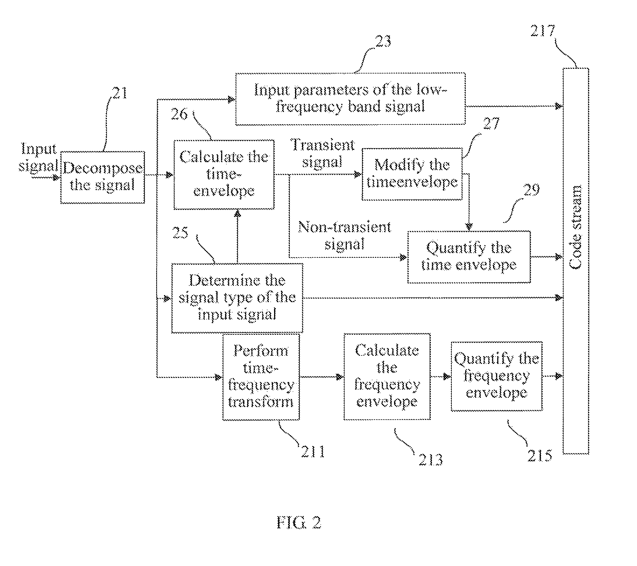
[0042]FIG. 2 is a flow chart of a transient signal encoding method according to the present invention. As shown in FIG. 2, the method includes the following steps.

[0043]In Step 21, an input signal is decomposed into a low-frequency band signal and a high-frequency band signal; and as for the low-frequency band signal, Step 23 is performed, and as for the high-frequency band signal, Step 25 is performed.

[0044]In Step 23, parameters of the low-frequency band signal in the input signal are input into a bitstream; and Step 217 is performed.

[0045]In this embodiment, the parameters of the low-frequency band signal (broadband signal) are input into the bitstream through an encoder.

[0046]In Step 25, a signal type of the input signal (the high-frequency signal) is determined, and signal type information is input into the bitstream, in which the signal type information is configured to indicate whether the input signal (that is, the signal being currently encoded) is a transient signal or a n...

third embodiment

[0086]FIG. 4 is a flow chart of a transient signal decoding method according to the present invention. As shown in FIG. 4, the method includes the following steps.

[0087]In Step 41, a sub-frame where a time envelope having a maximal amplitude value (that is, a maximal time envelope) is located is obtained from time envelopes of all sub-frames of a pre-obtained signal having a signal type of a transient signal, in which the sub-frame is the reference sub-frame described in the embodiments of the present invention.

[0088]The modification of the time envelope of the transient signal may be performed at the encoding end or the decoding end. In this embodiment, the time envelope is modified according to the characteristics of the transient signal at the decoding end, such that in the modified time envelope, the difference between the amplitude value of the time envelope having the maximal amplitude value of the sub-frames of the transient signal and the amplitude values of other time envel...


PUM


Abstract

A transient signal encoding method and device, decoding method and device, and processing system, where the transient signal encoding method includes: obtaining a reference sub-frame where a maximal time envelope having a maximal amplitude value is located from time envelopes of all sub-frames of an input transient signal; adjusting an amplitude value of the time envelope of each sub-frame before the reference sub-frame in such a way that a first difference is greater than a preset first threshold, in which the first difference is a difference between the amplitude value of the time envelope of each sub-frame before the reference sub-frame and the amplitude value of the maximal time envelope; and writing the adjusted time envelope into bitstream.

Description

CROSS-REFERENCE TO RELATED APPLICATIONS[0001]This application is a continuation of International Application No. PCT / CN2009 / 076194, filed on Dec. 29, 2009, which claims priority to Chinese Patent Application No. 200810247009.7, filed on Dec. 29, 2008, both of which are hereby incorporated by reference in their entireties.FIELD OF THE INVENTION[0002]The present invention relates to the field of communication technologies, and in particular, to a transient signal encoding method and device, decoding method and device, and processing system.BACKGROUND OF THE INVENTION[0003]Due to the limitation of the number of bit rates for encoding speech signals and the influence of human auditory characteristics, low-frequency band information in a speech signal is always encoded first in an audio encoding algorithm. Compared with narrow-band speech, wide-band speech has the characteristics of being fuller and more natural; therefore, the acoustic quality can be improved by increasing the bandwidth...

Claims


Application Information

Patent Timeline
Patent Type & Authority Patents(United States)
IPC IPC(8): H03M1/12
CPCG10L19/025G10L19/02G10L19/03H03M7/30
Inventor LIU, ZEXINCHEN, LONGYINMIAO, LEIHU, CHENXIAO, WEITADDEI, HERVE MARCELZHANG, QING
Owner CRYSTAL CLEAR CODEC LLC
Why Eureka
Try Eureka