Method for identifying color in machine and computer vision applications
Inactive Publication Date: 2011-11-22
VISION INTERFACE TECH
View PDF23 Cites 2 Cited by
Summary
Abstract
Description
Claims
Application Information
AI Technical Summary
This helps you quickly interpret patents by identifying the three key elements:
Problems solved by technology
Method used
Benefits of technology
Benefits of technology
[0018]CMYK uses subtractive color mixing in used printing process. It is possible to achieve a large range of colors seen by humans by combining cyan, magenta, and yellow transparent dyes / inks on a white substrate. Often a fourth black is added to improve reproduction of some dark colors. CMYK stores ink values for cyan, magenta, yellow, and black. There are many CMYK color spaces for different sets of inks, substrates, and press characteristics.
[0026]It is clear from the prior art that traditional grayscalemachine vision systems are being used successfully in a wide variety of inspection and process control applications for the electronic, automotive, food products, packaging, pharmaceutical, and recycling industries. However, the use of color machine vision systems in these industries has only been applicable to well controlled immediate environments or surroundings. It is also clear that prior art relied on matching color to a reference color image or template. A color machine and computer visionsystem that can make robust identification of color under varying lighting and changing image shift, scale, and rotation conditions is desirable. Machine vision systems use specialized and expensive hardware and software and therefore their use has been limited to industrial applications. With the advance of inexpensive color webcams, it is also desirable to find use for computer vision systems in cost sensitiveconsumer applications.
[0028]It would also be desirable to provide an improved method for effectively and accurately identifying color of a target image for machine and computer vision applications under varying lighting and image conditions.
Of course, there are many color perceptions that by definition cannot be pure spectral colors.
Results obtained when mixing additive colors are often counterintuitive for people accustomed to the more everyday subtractive colorsystem of pigments, dyes, inks, and other substances which present color to the eye by “reflection” rather than emission.
CIE is the most accurate color space but is too complex for everyday uses.
However, the use of color machine vision systems in these industries has only been applicable to well controlled immediate environments or surroundings.
Machine vision systems use specialized and expensive hardware and software and therefore their use has been limited to industrial applications.
Method used
Image
Click on the blue label to locate the original text in one second.
Reading with bidirectional positioning of images and text.
Examples
example 1
[0061]Consider Two Pixels with the Following Components:
[0063]In ratio space values: Pixel 1: (r, g, b)=1.0, 0.238, 0.190 and Pixel 2: (r, g, b)=1.0, 0.904, 0.381 then the distance equation for the Pixel1 and Pixel2 become:
[0064]The result of distance equation is “0” i.e. the Pixel 1 passes the threshold test and is identified as a rich shade of red and the output of the filter is set to black. On the other hand, Pixel 2 does not pass the threshold test and is categorized as a fade or pale shade or unidentified color, therefore, the output of the filter is set to white (i.e. 255).
[0065]There are several ways for defining a filter and setting threshold values. For example, a pixel representing a green color might register the following values in the ra...
example 2
[0068]The camera output might register (R, G, B)=0.6, 0.8, 92.8 and (r, g, b)=0.006, 0.008, 1.0 for a blue spot over a sunny part of the field of view or (R, G, B)=3.2, 14.3, 63.5 and (r, g, b)=0.05, 0.225, 1.0 over a shadowy region of the field of view. The camera output for a red spot might register (R, G, B)=99.6, 0.4, 0.4 and (r, g, b)=1.0, 0.004, 0.004 over a sunny part of the field of view or (R, G, B)=64.7, 17.8, 4.6 and (r, g, b)=1.0, 0.275, 0.07 over a shadowy region of the field of view. While the original (R, G, B) values might fluctuate significantly from sunny regions to shadowy spots of the field of view, the ratio space values make it easy to identify the color of interest.
[0069]Another advantage of the present method in identifying color is the ability to optimize the “camera parameters” for varying lighting conditions. Camera parameters such as: gain, brightness, contrast, saturation, sharpness, white balance, backlight compensation, etc. can be optimized for a give...
PUM
Abstract
A method for identifying color in a target creates a ratio color space by determining the largest color component value of each pixel in an image and creating a ratio of all of the color component value with the largest component value for each pixel. The ratio for the color component of each pixel undergoes a threshold test to identify each color component as a rich shade or a fade shade. The ratio space color components are converted to a black and white image. Color information of adjacent pixels are clumped together to form blobs of the same color. The blobs are filtered by shape, color, location, or orientation and sorted to find targets that consist of a predefined pattern with the desired characteristics.
Description
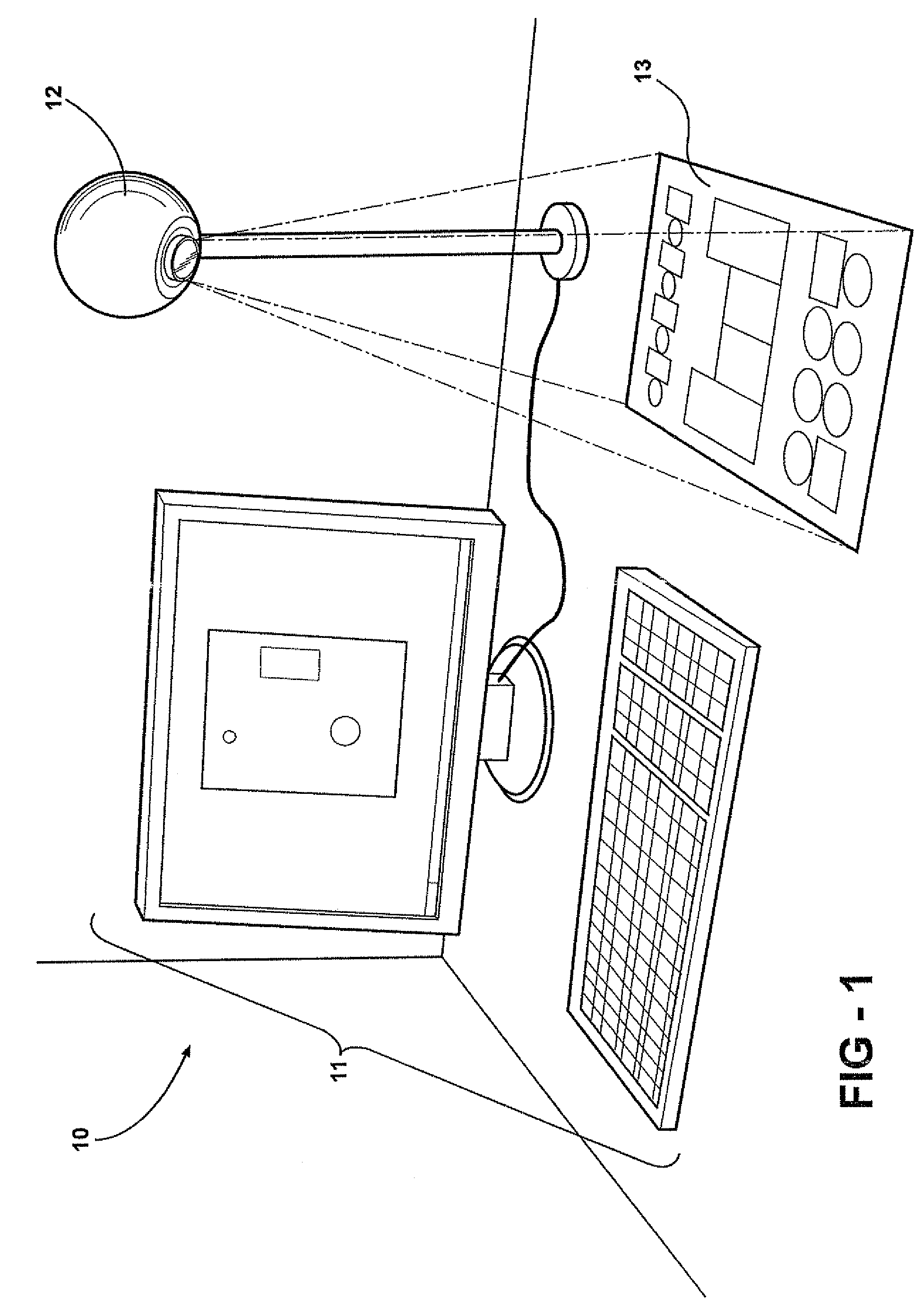
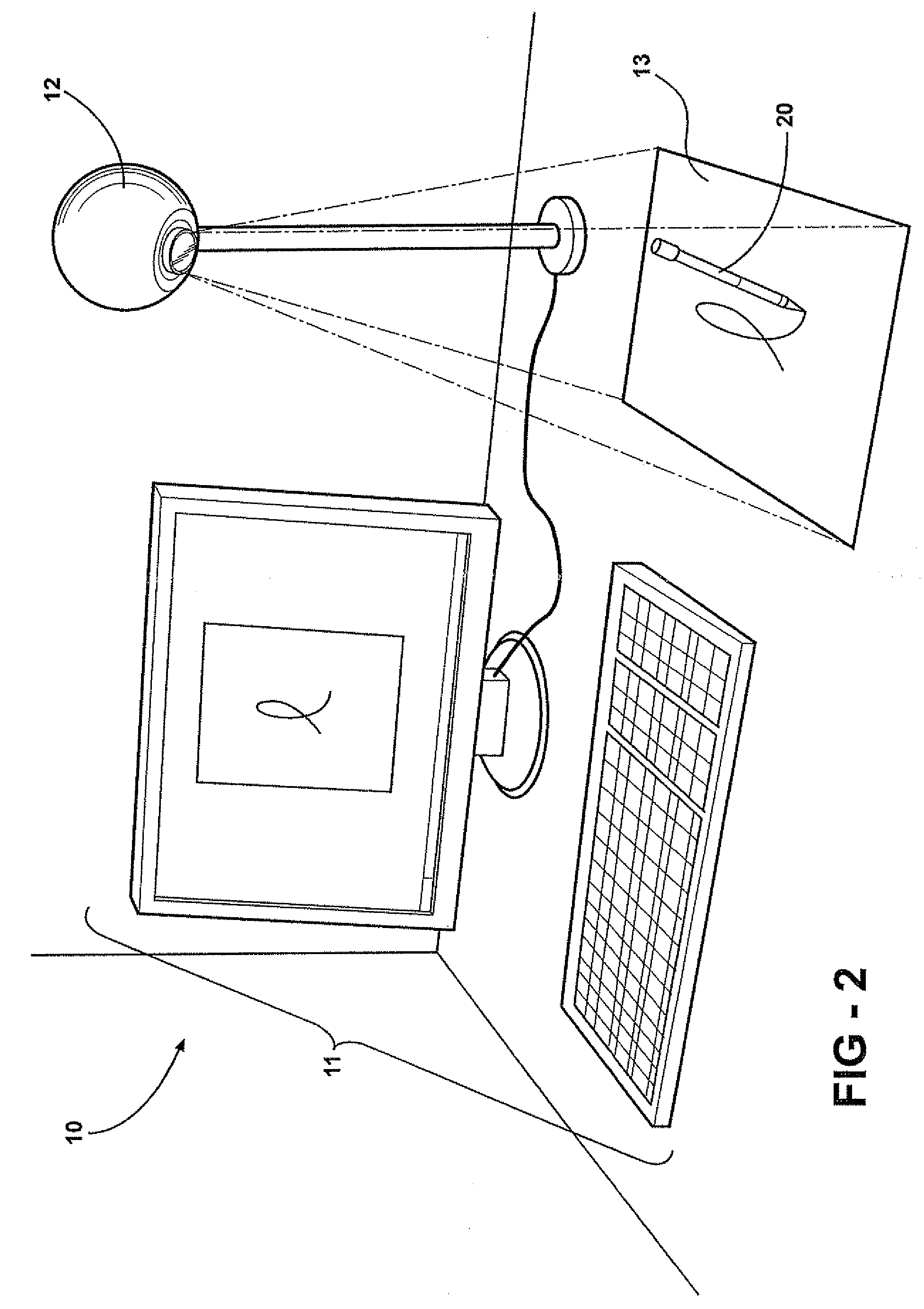
CROSS REFERENCE TO CO-PENDING APPLICATION[0001]This application claims priority benefit to the filing date of co-pending U.S. Provisional Patent Application Ser. No. 60 / 917,966, filed May 15, 2007.BACKGROUND[0002]The present invention relates to a method for identifying colors in an image. The image is in the field of view of a camera or cameras and the camera is an interface to a computer for machine and computer vision applications. The invention also relates to a triggering mechanism in the field of view by identifying colors which allows the camera to be used as an interface with a computer for consumer applications.[0003]Machine vision, commonly called automated inspection, has been used in manufacturing processes to improve productivity and quality. On a typical production line, a sensor detects a part and signals a video camera positioned above or to the side of the inspection point to capture an image and send it to a machine vision processor. Using a combination of machine ...
Claims
Application Information
Patent Timeline
Application Date:The date an application was filed.
Publication Date:The date a patent or application was officially published.
First Publication Date:The earliest publication date of a patent with the same application number.
Issue Date:Publication date of the patent grant document.
PCT Entry Date:The Entry date of PCT National Phase.
Estimated Expiry Date:The statutory expiry date of a patent right according to the Patent Law, and it is the longest term of protection that the patent right can achieve without the termination of the patent right due to other reasons(Term extension factor has been taken into account ).
Invalid Date:Actual expiry date is based on effective date or publication date of legal transaction data of invalid patent.

