
Face recognition auto focus apparatus for a moving image

a technology of face recognition and moving images, applied in the direction of camera focusing arrangement, printers, instruments, etc., can solve the problems of not being put into practical use, applying face recognition to autofocus, etc., and achieve the effect of shortening the distance of the lens to be moved under focus control

Active Publication Date: 2011-11-29
SONY CORP
View PDF39 Cites 14 Cited by
  • Summary
  • Abstract
  • Description
  • Claims
  • Application Information

AI Technical Summary

Benefits of technology

[0035]The control unit may, with a focus control execution period within the set limits, based on the calculated subject distance employing the face detected by the face-detecting unit, alleviate the limits, in the case of detecting movement of a screen or face frame which is equal to or greater than a predetermined threshold, or input of operating information of any of zooming, panning, and tilting.
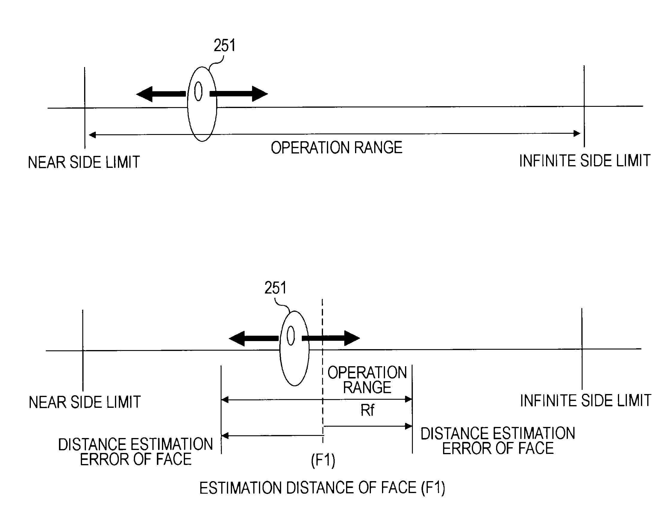
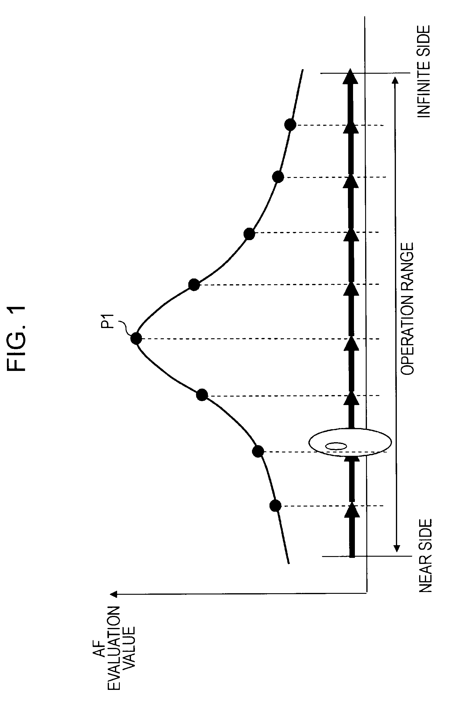
[0041]With the arrangement of an embodiment of the present invention, with autofocus processing of an imaging apparatus, a face region is detected from an input image, subject distance is calculated based on the size of the detected face, and a focus position is estimated based on the calculated subject distance information. Further, a focus lens operation range which is shorter than the overall operation range of a focus lens is set based on the estimated focus position, and the focus lens is moved within the set lens operation range to determine a focus lens set position. According to the present arrangement, the distance of the lens to be moved under focus control can be set shorter, thereby realizing high-speed focus control.

Problems solved by technology

As described above, an arrangement is frequently employed with digital cameras, wherein a face is recognized from an image at an imaging apparatus, and a ranging area is set to the position of the recognized face to make it possible to focus on the face, but with video cameras, the movement of a face region itself occurs, so applying face recognition to autofocus at the time of taking a moving image frequently collapses, so the current state is that this arrangement has not been put into practical use.

Method used


Image

  • Face recognition auto focus apparatus for a moving image
  • Face recognition auto focus apparatus for a moving image
  • Face recognition auto focus apparatus for a moving image

Examples


Embodiment Construction

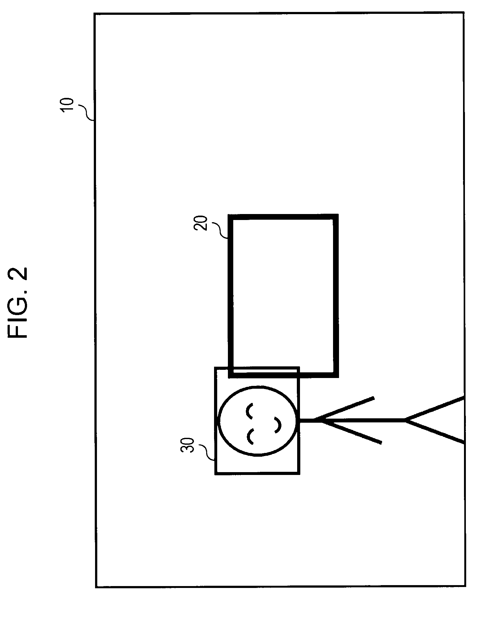
[0061]Hereafter, description will be made regarding the details of an imaging apparatus, imaging apparatus control method, and computer program according to an embodiment of the present invention with reference to the drawings. With an embodiment of the present invention, a person's face is detected from shot image frames to perform focus control as to the detected face at the time of shooting with an imaging apparatus capable rapid correct autofocus as to a target subject, and particularly with an imaging apparatus serving as a video camera for taking a moving image.

[0062]FIG. 3 is a block diagram showing an example of the functional configuration of an imaging apparatus 100 as a data processing apparatus according to an embodiment of the present invention. An imaging lens 101 internally includes a zoom lens for consecutively changing focal distance, a focus lens for adjusting focus, aperture diaphragm for changing the aperture, an ND mechanism for inserting an adjustment ND (Neutr...


PUM


Abstract

A data processing device includes: a face-detecting unit to detect a face region from an input image input from an imaging unit which images a subject including a face; a setting unit to calculate subject distance based on the face size of the face detected by the face-detecting unit, and set limits as a focus lens operation range before and after a focus lens position with the calculated subject distance as focal distance; a detecting unit to move a focus lens within the limits set by the setting unit, and detect a focal point where a detection value corresponding to the contrast intensity obtained from a face frame including the face detected by the face-detecting unit is not smaller than a threshold; and a control unit to determine, in a case wherein a focal point has been detected within predetermined set time, the focal point thereof as a focus position.

Description

CROSS REFERENCES TO RELATED APPLICATIONS[0001]The present invention contains subject matter related to Japanese Patent Application JP 2007-238694 filed in the Japanese Patent Office on Sep. 14, 2007, the entire contents of which are incorporated herein by reference.BACKGROUND OF THE INVENTION[0002]1. Field of the Invention[0003]The present invention relates to an imaging apparatus, imaging apparatus control method, and computer program, and more particularly relates to an imaging apparatus, imaging apparatus control method, and computer program whereby rapid and accurate autofocus processing as to a target subject.[0004]2. Description of the Related Art[0005]With a recent great number of imaging apparatuses such as still cameras, video cameras, and so forth, an autofocus (AF) mechanism for automatically focusing on a subject is implemented.[0006]As for this autofocus control technique, a technique has been known wherein a contrast level of imaged data obtained through a lens is dete...

Claims


Application Information

Patent Timeline
Patent Type & Authority Patents(United States)
IPC IPC(8): G03B13/00G03B3/00
CPCG03B13/30G03B13/36G06K9/00228H04N5/23212H04N5/23219H04N5/23293G06V40/161H04N23/673H04N23/61H04N23/611H04N23/635
Inventor KUMAGAI, FUMIHIROKAWAI, TAKASHITRITEYAPRASERT, SOROJ
Owner SONY CORP
Learn More