Method and system for turbocharging an engine

a technology of turbocharging and engine, applied in the direction of machines/engines, electric control, combustion air/fuel air treatment, etc., can solve the problems of increasing engine emissions, reducing engine efficiency during engine start, and more difficult to meet engine emissions, so as to increase engine efficiency, reduce engine displacement, and boost the effect of engin

Active Publication Date: 2011-12-06
FORD GLOBAL TECH LLC
View PDF22 Cites 71 Cited by
  • Summary
  • Abstract
  • Description
  • Claims
  • Application Information

AI Technical Summary

Benefits of technology

[0002]One way to increase engine efficiency is to reduce engine displacement and boost the engine. However, placing a turbine in an exhaust system can increase engine emissions and reduce engine efficiency during an engine start. In particular, engine emissions can be increased since the turbocharger may sink engine exhaust heat during an engine start rather than passing the exhaust heat to a catalyst to promote oxidation and reduction of exhaust gas constituents. Further, engine efficiency can be reduced when spark is retarded or air mass flow through the engine is increased to warm the mass of the turbocharger. Thus, engine boosting can make it more difficult to meet engine emissions and improve engine efficiency during engine starting.
[0004]Engine efficiency can be increased while engine emissions are reduced by separating the exhaust ports of a cylinder and separately processing blow down (e.g., expanding exhaust gases in a cylinder before time when a piston of the cylinder reaches bottom dead center expansion stroke) and residual exhaust gases (e.g., gases that remain in the cylinder after blow-down). In particular, exhaust energy can be transferred from the blow-down gases to operate a turbocharger or to reduce engine friction by quickly warming the engine via an exhaust heat recovery device such as a gas-to-liquid heat exchanger. At the substantially same time, residual gases are directed from a second exhaust port of the cylinder to heat a catalyst, thereby reducing engine emissions. In this way, exhaust gases can be used more efficiently than simply directing all the exhaust gas of a cylinder to a turbocharger.
[0005]The present description may provide several advantages. For example, the approach may improve fuel economy and reduce particulate emissions by decreasing engine warm-up time. Further, the method can reduce engine emissions since at least a portion of cylinder exhaust gases are directly routed from the cylinder to the catalyst. Further still, the average exhaust gas pressure supplied to the turbocharger can be increased to improve turbocharger output.

Problems solved by technology

However, placing a turbine in an exhaust system can increase engine emissions and reduce engine efficiency during an engine start.
Thus, engine boosting can make it more difficult to meet engine emissions and improve engine efficiency during engine starting.

Method used


Image

  • Method and system for turbocharging an engine
  • Method and system for turbocharging an engine
  • Method and system for turbocharging an engine

Examples


Embodiment Construction

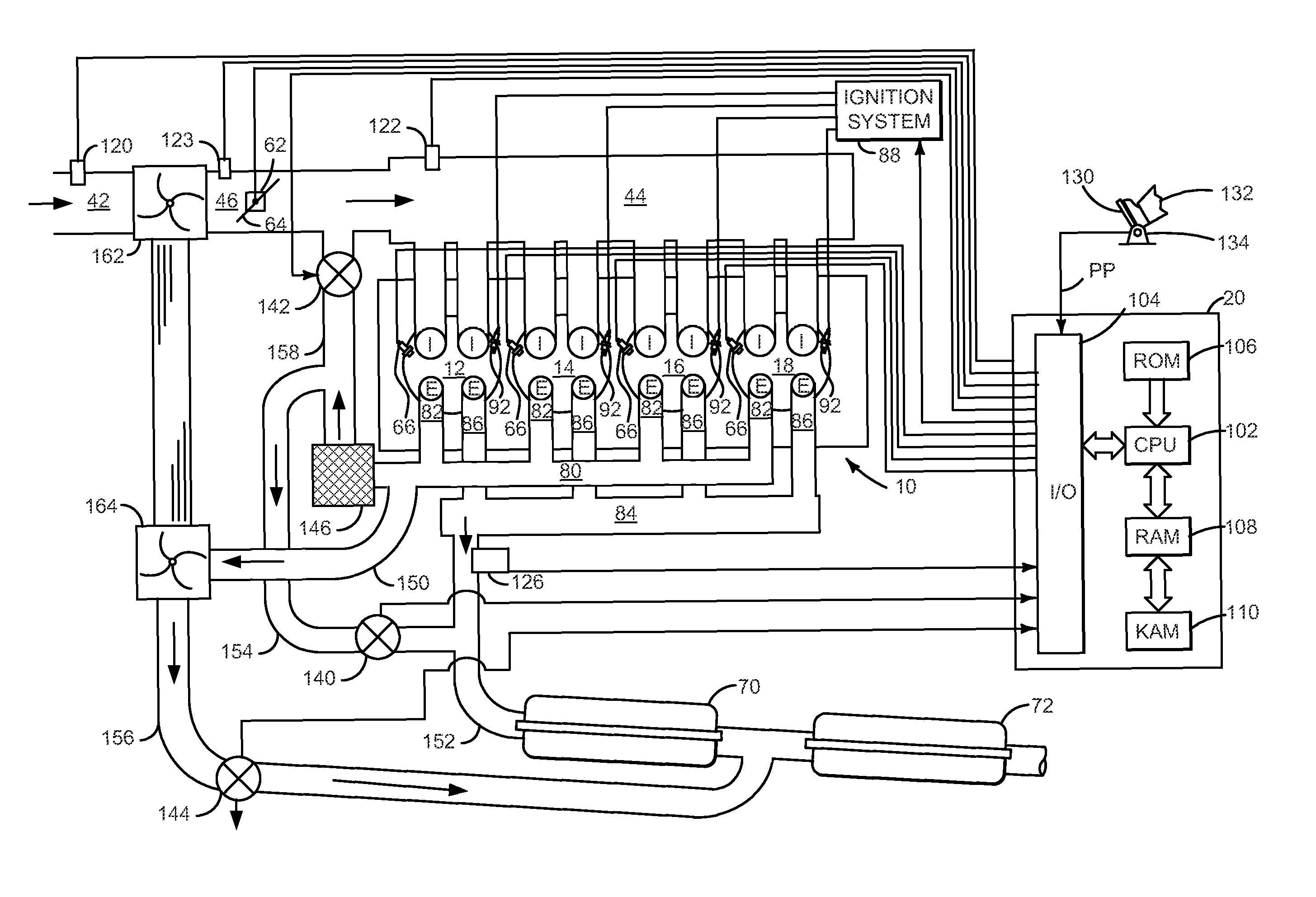
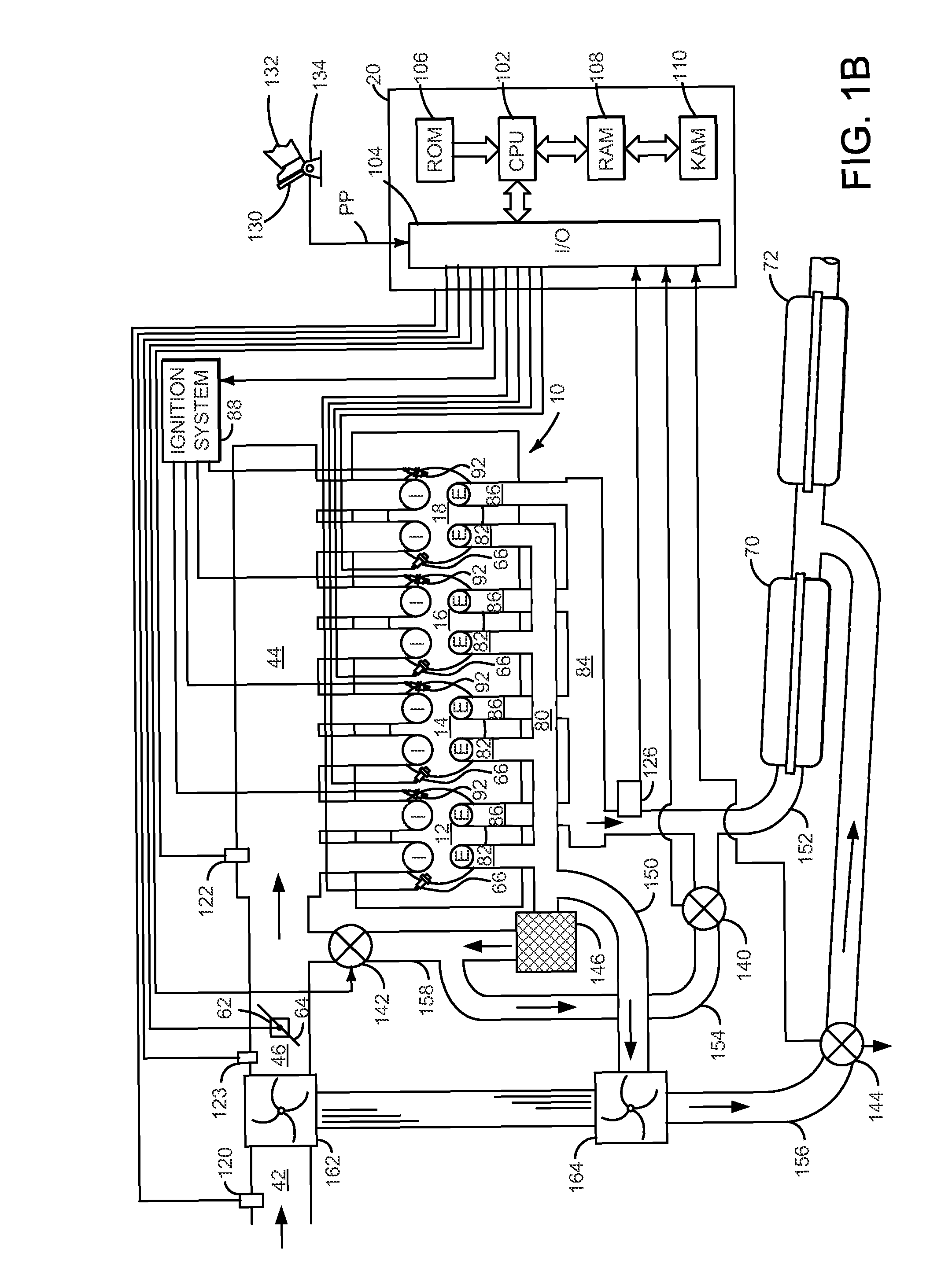
[0015]The present description is related to operating an engine. In one non-limiting example, the engine may be configured as illustrated in FIGS. 1A and 1B. In one example, blow-down gases of a cylinder are separated from residual cylinder gases and the engine is operated according to the methods of FIGS. 4A-4B providing the signals of FIGS. 2-3.

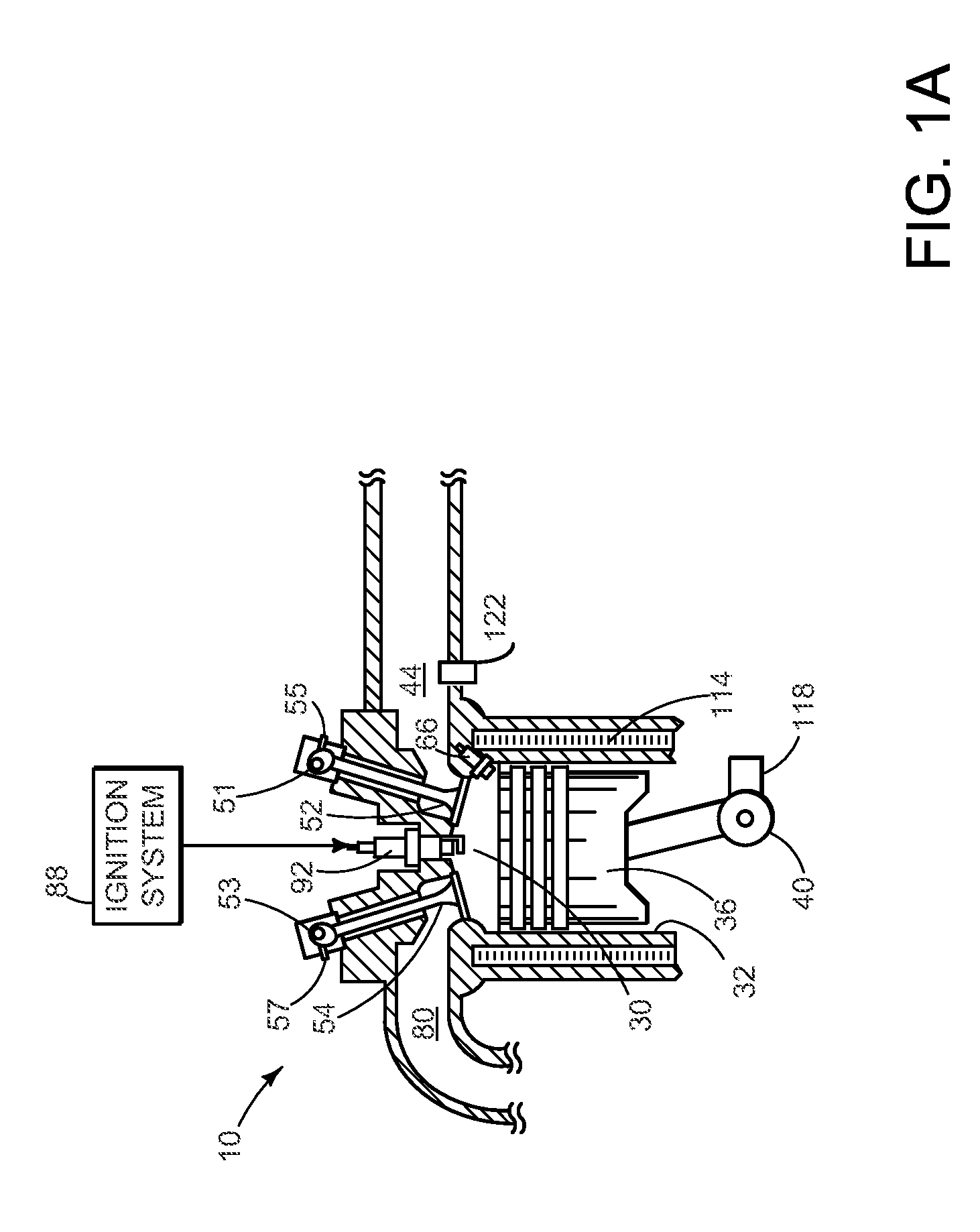
[0016]Referring to FIG. 1A, a single cylinder of an internal combustion engine 10 is shown. Internal combustion engine 10 is comprised of a plurality of cylinders as shown in FIG. 2. Engine 10 includes combustion chamber 30, coolant sleeve 114, and cylinder walls 32 with piston 36 positioned therein and connected to crankshaft 40. Combustion chamber 30 is shown communicating with intake manifold 44 and exhaust manifold 80 via respective intake valves 52 and exhaust valves 54. Each intake and exhaust valve may be operated by an intake cam 51 and an exhaust cam 53. Alternatively, one or more of the intake and exhaust valves may be operated by...


PUM


Abstract

A method for improving operation of a turbocharged engine is presented. In one embodiment, the method may reduce engine emissions and improve engine efficiency during an engine start.

Description

FIELD[0001]The present description relates to a method for improving operation of a turbocharged engine. The method may be particularly useful for reducing engine emissions and increasing engine efficiency after a cold start.BACKGROUND AND SUMMARY[0002]One way to increase engine efficiency is to reduce engine displacement and boost the engine. However, placing a turbine in an exhaust system can increase engine emissions and reduce engine efficiency during an engine start. In particular, engine emissions can be increased since the turbocharger may sink engine exhaust heat during an engine start rather than passing the exhaust heat to a catalyst to promote oxidation and reduction of exhaust gas constituents. Further, engine efficiency can be reduced when spark is retarded or air mass flow through the engine is increased to warm the mass of the turbocharger. Thus, engine boosting can make it more difficult to meet engine emissions and improve engine efficiency during engine starting.[0...

Claims


Application Information

Patent Timeline
Patent Type & Authority Patents(United States)
IPC IPC(8): F02B33/44F02M25/06F02M25/07F01L1/34F01N5/04
CPCF02D13/0249F02M25/0706F02M25/0707F02M25/073F02M25/0731F02M25/0751F02D43/00F02B37/18F02B37/00F02D13/02F02M35/1085F02D13/0257Y02T10/121Y02T10/18F02M25/0718F02M25/0715F02D13/0242F05B2220/40F02B2075/1816F02M25/0726F02M26/05F02M26/27F02M26/28F02M26/44F02M35/112F02M26/04F02M26/13F02M26/15F02M26/22Y02T10/12F02B33/44
Inventor ULREY, JOSEPH NORMANPURSIFULL, ROSS DYKSTRA
Owner FORD GLOBAL TECH LLC
Why Eureka
Try Eureka