
Aircraft structure

a technology for aircraft and structure, applied in the field of aircraft structure, can solve the problems of saving time and complexity during the assembly procedure, and achieve the effects of saving time and complexity, simple and reliable method, and reducing assembly tim

Active Publication Date: 2011-12-06
AIRBUS OPERATIONS LTD
View PDF11 Cites 20 Cited by
  • Summary
  • Abstract
  • Description
  • Claims
  • Application Information

AI Technical Summary

Benefits of technology

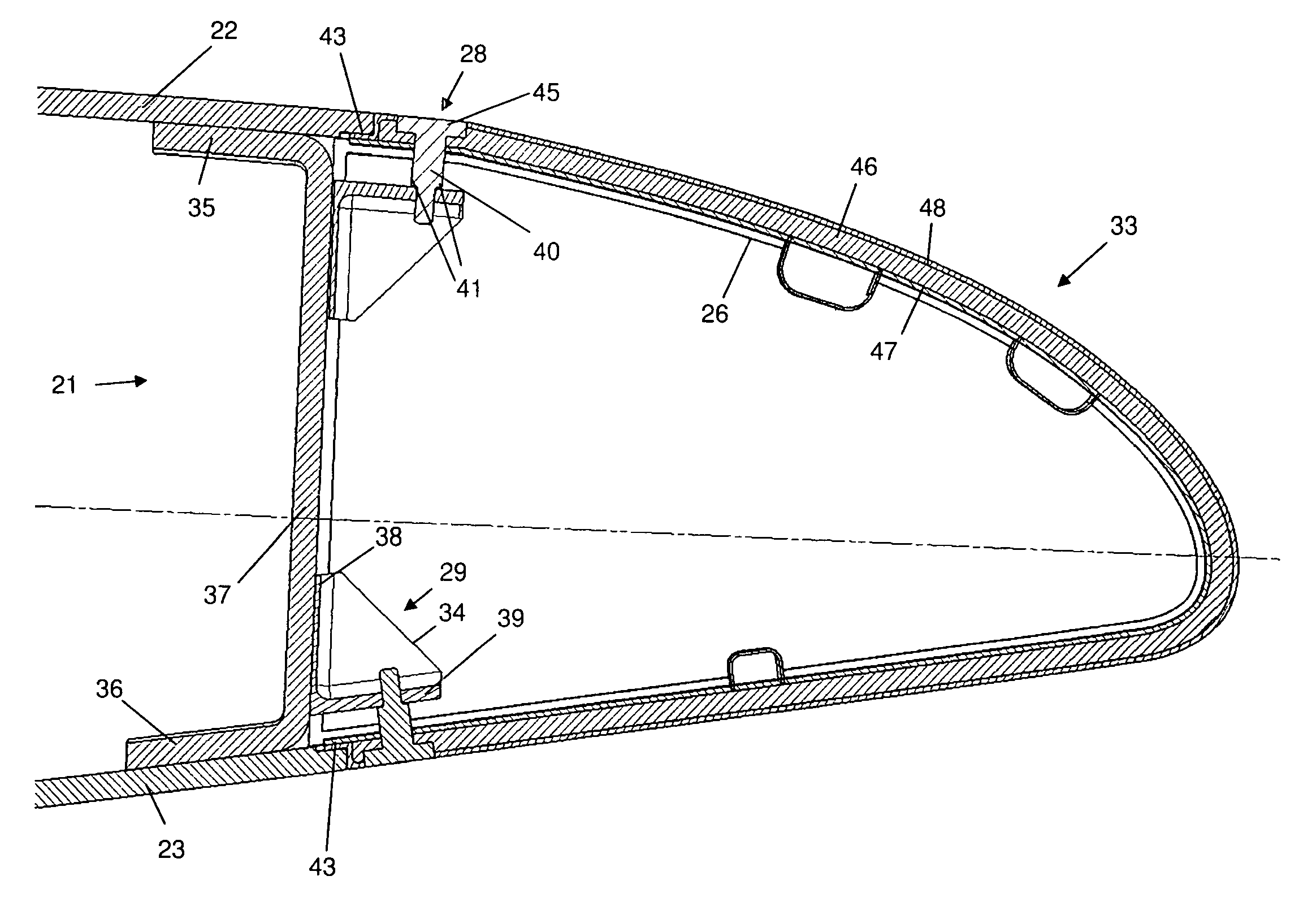
The invention provides an aircraft structure that includes a spar, primary cover, secondary cover, bracket, and spacer. The spacer can be adjusted to control the distance between the secondary cover and the bracket so that the primary and secondary covers together form a continuous external aerodynamic surface. This design eliminates the need for butt-strap fasteners, reduces assembly time, and saves weight over conventional structures. The spacer is detachable from the secondary cover and bracket, making assembly and adjustment easy. The secondary cover can be positioned on either the front or rear side of the spar, and the bracket can be positioned at various locations along the spar.

Problems solved by technology

This saves time and complexity during the assembly procedure.

Method used


Image

  • Aircraft structure
  • Aircraft structure
  • Aircraft structure

Examples


Embodiment Construction

)

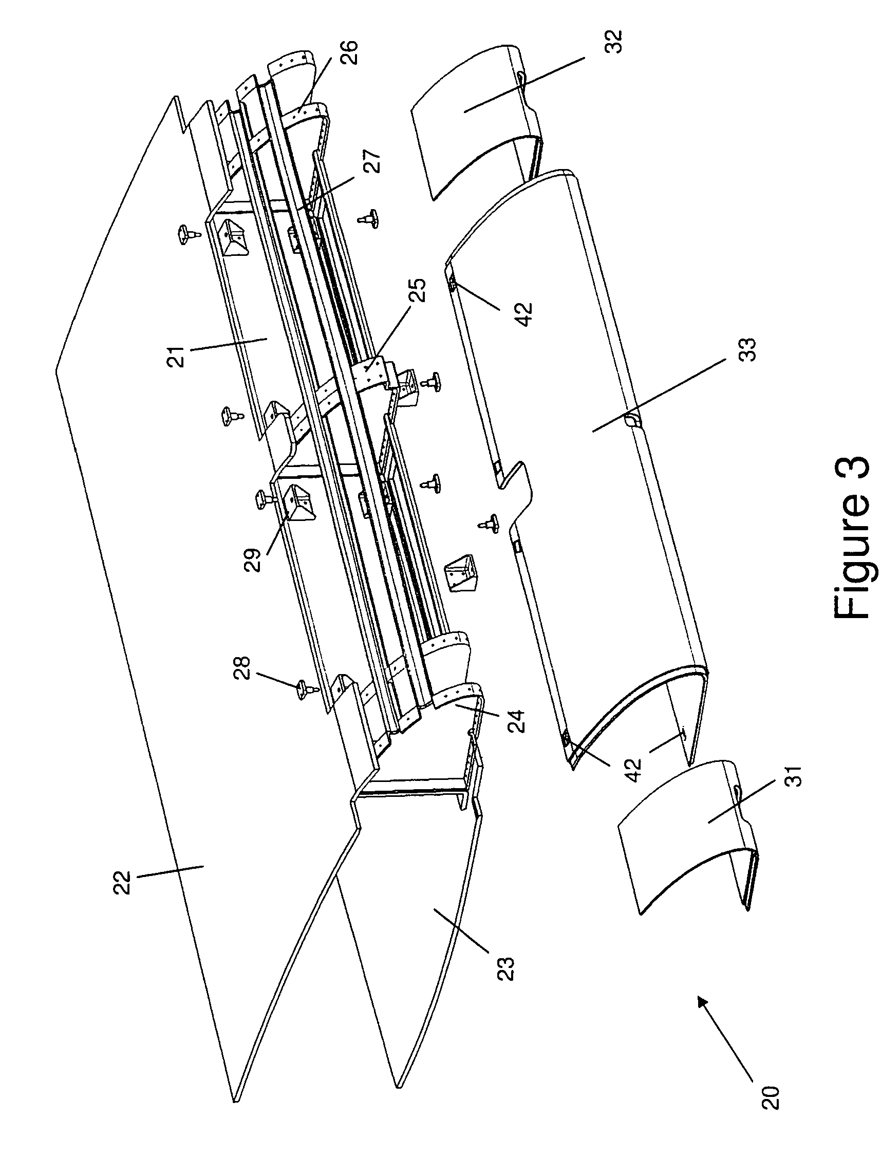
[0023]FIGS. 3-5 show part of the leading edge 20 of an aircraft wing. The wing comprises a front spar 21 and a rear spar (not shown). Upper and lower covers 22, 23 are attached to the spars and extend between them to form the upper and lower boundaries of a wing box, which is the primary structure of the wing.

[0024]Two sets of slat track ribs 24, 26 are bolted to the front spar 21 and are used to carry a movable slat (not shown). An intermediate slat rib 25 is bolted to the front spar 21 and assists in maintaining the position of the slat (not shown) whilst in its retracted position. Cable troughs 27 are also bolted to the ribs 24, 25, 26 and extend in a span-wise direction along the wing. Electrical cables (not shown) are laid in the cable troughs 27.

[0025]To achieve a smooth aerodynamic surface across the leading edge of the wing, the secondary structures forward of the front spar 21 are housed within D-nose covers 31-33. The slat track covers 31, 32 are attached to and cover the...


PUM

PropertyMeasurementUnit
distanceaaaaaaaaaa
structureaaaaaaaaaa
aerodynamicaaaaaaaaaa

Abstract

An aircraft structure comprising: a spar; a primary cover attached to the spar and extending on a first side of the spar; and a secondary cover positioned on a second side of the spar and partially overlapping an internal surface of the primary cover. A bracket is attached to the spar, and a spacer is provided between the secondary cover and the bracket. The spacer is sized so that the primary and secondary covers together form a substantially continuous external aerodynamic surface. The structure provides an alternative to conventional butt-strap arrangements.

Description

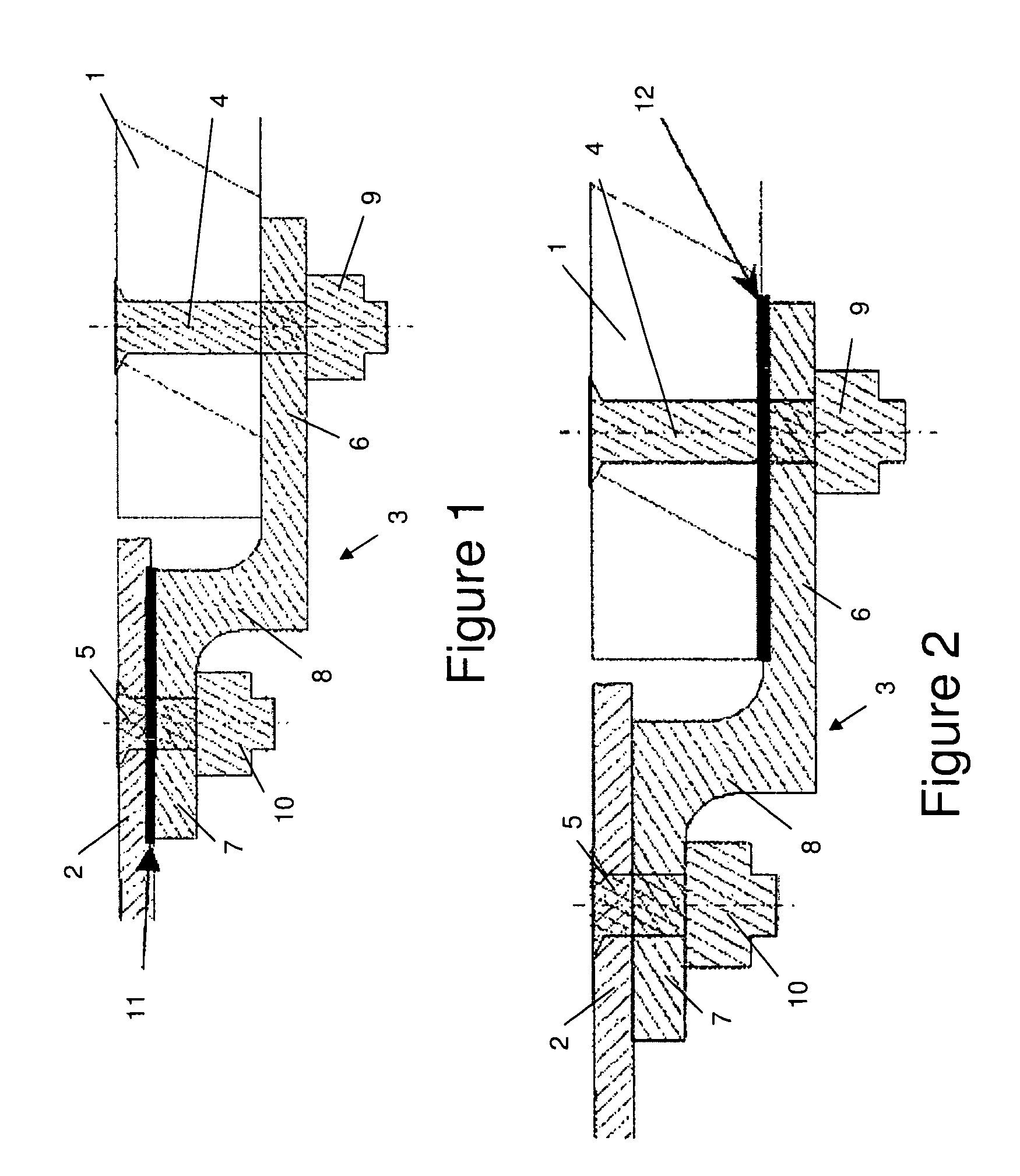
[0001]This application claims priority to Great Britain Patent Application No. 0805963.6, filed 2 Apr. 2008, the entire content of which is hereby incorporated by reference.FIELD OF THE INVENTION[0002]The present invention relates to an aircraft structure comprising: a spar; a primary cover attached to the spar and extending on a first side of the spar; and a secondary cover positioned on a second side of the spar. In particular, the invention relates to a structure and assembly method which ensures that the covers form a substantially continuous external aerodynamic surface.BACKGROUND OF THE INVENTION[0003]Conventional aircraft wings comprise a wing box with front and rear spars. Upper and lower wing covers are attached to the spars and extend between them to form the upper and lower boundaries of the wing box. Leading and trailing edge structures, such as panels or D-nose covers, are typically attached to the upper and lower covers with butt straps. FIGS. 1 and 2 illustrate conven...

Claims


Application Information

Patent Timeline
Patent Type & Authority Patents(United States)
IPC IPC(8): B64C1/00
CPCB64C3/185B64C3/26B64C3/28Y10T29/49771Y10T29/49622
Inventor DOUGLAS, PAUL
Owner AIRBUS OPERATIONS LTD
Learn More