Multiple degrees of freedom motion system

a motion system and degree of freedom technology, applied in the direction of mechanical control devices, instruments, manual control with single controlling member, etc., can solve the problems of inability to provide nanometric motion quality, high cost, maintenance, and high complexity of motion systems, and achieve the effect of facilitating assembly with sensors and minimizing undesired sensing errors

Inactive Publication Date: 2011-12-06
AWTAR SHORYA
View PDF5 Cites 6 Cited by
  • Summary
  • Abstract
  • Description
  • Claims
  • Application Information

AI Technical Summary

Benefits of technology

[0022]In one non-limiting aspect of this invention, a three-DoF (X, Y and Z) motion system that provides large motion range as well as high motion quality (precision, accuracy, and bi-directional repeatability) using commonly available components, is proposed. The three DoF represent translational motions along the X, Y and Z directions. In the preferred embodiment, these three directions are mutually perpendicular.
[0028]The end-point measurement of the Motion Stage displacement, along any given DoF, with respect to Ground is obtained by dividing the sensing task into two achievable and easier sensing tasks. For measuring the displacement along the X DoF of the Motion Stage, first the large range X direction displacement of the first intermediate stage with respect to Ground is measured using a large measurement range and high resolution sensor, e.g., an LVDT or linear encoder. The prescribed sensing axis of this first sensor is made to align with the X direction displacement of the first intermediate stage. Next, the relative displacement of the Motion Stage in the X direction with respect to the first intermediate stage is measured using a sensor that allows off-axis motions, e.g. capacitance probes. Ideally, the entire X direction displacement of the first intermediate stage should be transmitted to the Motion Stage, and therefore there is substantially zero relative X direction displacement between the two. This is because the Motion Stage is constrained to move only in the Y and Z directions with respect to the first intermediate stage. However, since this constraint arrangement is implemented via real-life flexure constraint modules, described in further detail later, some deviation from ideal behavior is to be expected. Therefore, the relative X displacement between the Motion Stage and the first intermediate stage may not necessarily be zero, but is still generally very small. In particular for nanopositioning systems, it is important to measure this small motion. Thus, this second sensing task is successfully accomplished using a secondary sensor that provides high resolution and is tolerant to off-axis motions, even if it only capable of a small measurement range. This secondary sensor is located between the first intermediate stage and the Motion Stage, for example, the sensor may be rigidly mounted to the first intermediate stage and the sensor target maybe be rigidly mounted to the Motion Stage. The Motion Stage will have large Y and Z direction displacements with respect to the first intermediate stage, which are well tolerated by the secondary sensor.
[0031]Thus, in accordance with the present motion system invention, standard and commonly available sensors and actuators are employed in fashion that their capabilities are fully exploited and yet their limitations are accommodated, while meeting the overall objective of large range motion and high motion quality.
[0034]The Motion Stage, Ground and intermediate stages are all rigid, and may incorporate rigid extensions to facilitate assembly with sensors and actuators or to minimize undesired errors in sensing and actuation.

Problems solved by technology

Existing multi-DoF motion systems that provide nanometric motion quality are limited to hundreds of microns in motion range.
There have existed several challenges in achieving the large motion range and high motion quality simultaneously in multi-DoF motion systems.
Since the motion bearing is a challenging sub-system in itself, the resulting motion systems are typically characterized by high complexity, cost, and maintenance, and relatively large sizes.
Such serial designs are generally bulky and involve moving cables and actuators, which pose a challenge for high precision, speed-of-response, and ease of assembly.
Furthermore, air bearings need a constant supply of clean, high-pressure and low-humidity air, require periodic filter changes, and are not suitable for vacuum environment.
Despite utmost care in manufacturing and assembly, it is extremely difficult to improve the motion quality beyond 100 nm in these systems due to non-deterministic effects such as rolling of balls, sliding of surfaces, interface tribology, friction, and backlash.
This arrangement results in additional complexity in terms of parts, assembly and operation, and is still not able to achieve high precision or bi-directional repeatability.
However, this configuration is often bulky, and results in moving cables and actuators.
Moving cables are a source of disturbance and affect the motion quality, while moving actuators represent large moving masses that are detrimental to the dynamic performance of the motion system.
Furthermore, moving connections and actuators are difficult to implement in micro-scale applications, for example Micro Electro-Mechanical Systems (MEMS).
Compared to serial-kinematic designs, the main drawbacks of traditional parallel-kinematic designs include relatively smaller motion range, potential for over-constraint, and greater error motions.
Furthermore, parallel kinematic designs are not obvious and therefore are not as straightforward to design as serial kinematic designs.
The design of a large range parallel kinematic multi-DoF flexure bearing is non-obvious and challenging.
In general, this is a challenge because commonly available actuators and sensors have several limitations that restrict their use in multi-DoF nanopositioning systems.
These actuators typically do not tolerate any deviation from their actuation axis.
If a flexure bearing is such that the point of actuation for a certain DoF drifts off from the actuator's actuation axis, then upon assembly the motion system will very likely suffer from binding, ultimately leading to damage of the flexure bearing and / or the actuator.
However, any loads acting in directions other than the axis of the brittle ceramic stack, which is also the actuation axis, cause permanent damage to the actuator.
However, they provide relatively lower force capability, and therefore are impractical for many motion systems.
The sensing demands for large range, high motion quality, and multi-DoF motion systems are equally challenging.
These sensors are restricted to measurements along the sensing axis and are intolerant to any motion that deviates from the sensing axis.
However, with nanometric resolution, their measurement range is typically limited to hundreds of microns, and therefore do not readily meet the desired objective of large motion range and high motion quality.
Similarly, strain gauges and piezo-resistive sensors can provide nanometric resolution but at the cost of measurement range; moreover, they are also limited in terms of measurement accuracy.
Yet, it is an impractical option for desktop-size nanopositioning systems, given the associated equipment size, lack of compact packaging, and high cost.

Method used


Image

  • Multiple degrees of freedom motion system
  • Multiple degrees of freedom motion system
  • Multiple degrees of freedom motion system

Examples


Embodiment Construction

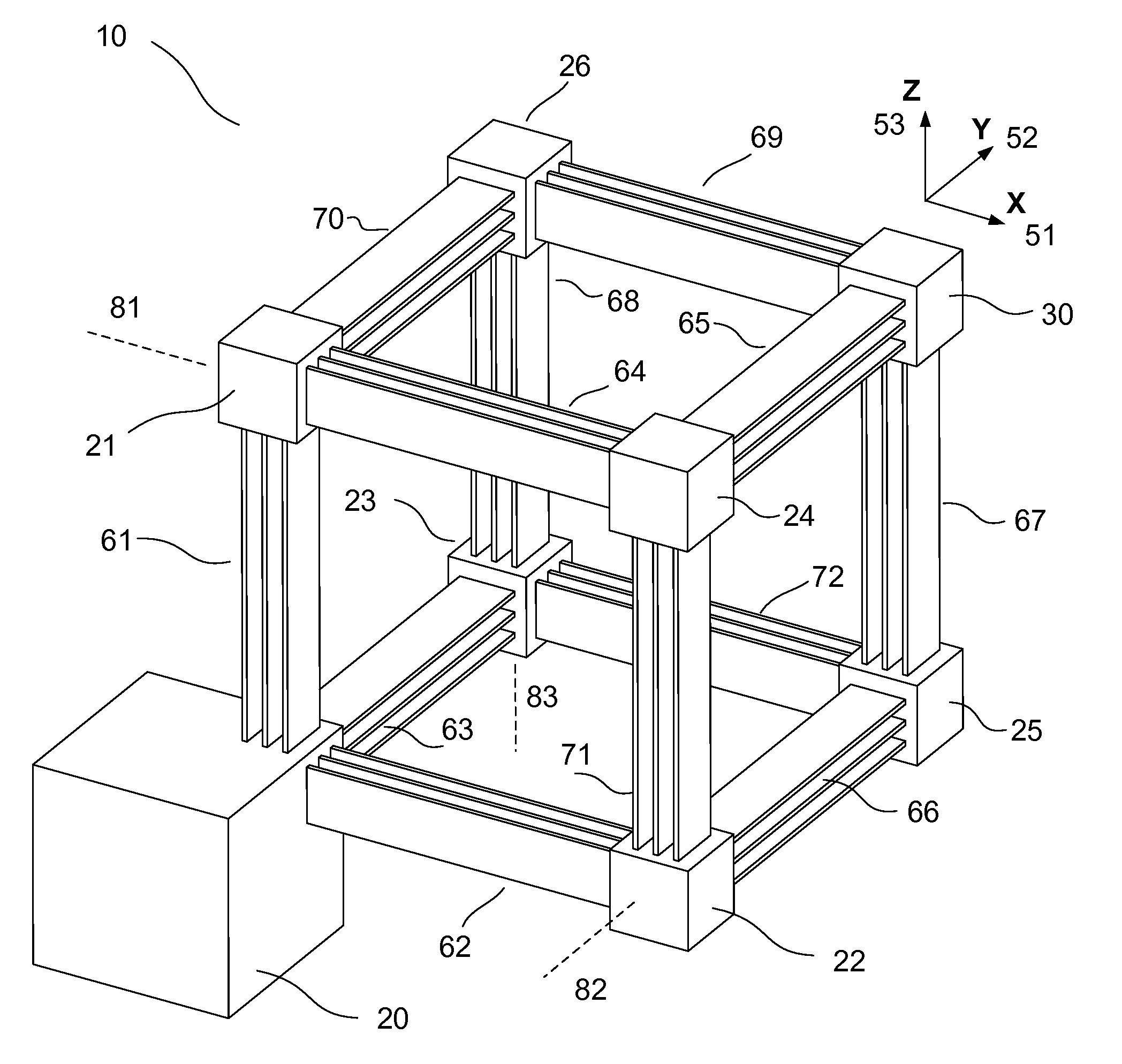
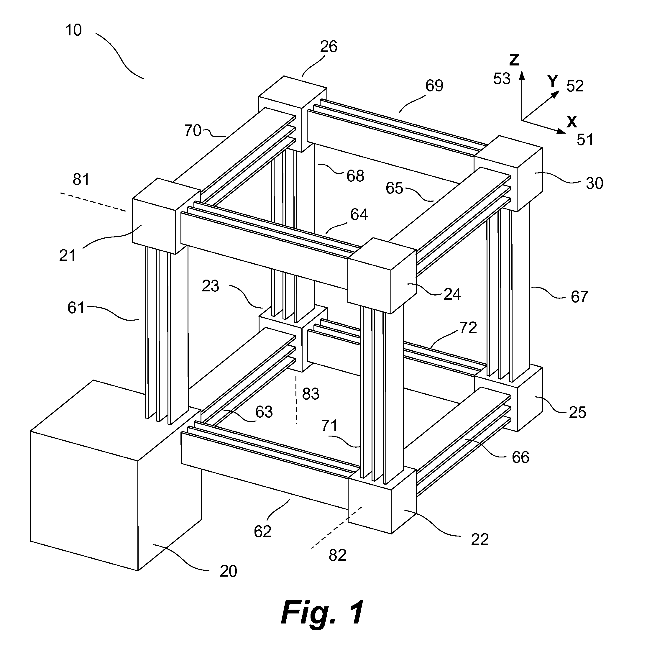
[0040]Referring now to FIG. 1, a motion system 10 is shown. The motion system 10 includes a Ground 20, which is the reference stage of the motion system, and a Motion Stage 30. The Motion Stage has three translational Degrees of Freedom with respect to Ground—X, Y and Z, indicated by 51, 52 and 53, respectively. Ground 20 is connected to a first intermediate stage 21 via a single DoF flexure constraint module 61, which only allows relative X translation between the two rigid stages. Ground 20 is also connected to a second intermediate stage 22 via a single DoF flexure constraint module 62, which only allows relative Y translation between the two. Ground 20 is further connected to a third intermediate stage 23 via a single DoF flexure constraint module 63, which only allows a relative Z translation between the two.

[0041]The first intermediate stage 21 is connected to a fourth intermediate stage 24 via a single DoF flexure constraint module 64, which only allows relative Y translation...


PUM


Abstract

A multiple degrees of freedom motion system comprising an arrangement of rigid stages, flexure constraint modules, actuators, and sensors. These components of the motion system are arranged and connected in a systematic fashion to provide a high degree of decoupling between the motion axes, suitable placement of ground-mounted actuators to actuate each motion axis, and suitable placement of sensors to allow end-point measurement along each motion axis. This arrangement of rigid stages, flexure constraint modules, actuators and sensors enables large motion range and high motion quality in the motion system, while using standard and commonly available components.

Description

FIELD OF THE INVENTION[0001]The present invention relates to a multiple degrees of freedom motion system comprising an arrangement of rigid stages, flexure constraint modules, actuators, and sensors.BACKGROUND OF THE INVENTION[0002]The present invention relates to a motion system comprising an arrangement of rigid stages, flexure constraint modules, actuators, and sensors. This unique arrangement results in large motion range along with high motion quality, while using standard and commonly available components. Motion quality, in the context of a motion system, is defined in terms of precision, also known as bi-directional repeatability of motion; accuracy, also known as trueness of motion; and, resolution, also known as minimum incremental motion.[0003]In the relevant art, a ‘motion system’ is understood to be a system that enables the motion of a rigid body or stage, commonly referred to as the Motion Stage, in a controlled fashion so as to follow a desired motion trajectory with...

Claims


Application Information

Patent Timeline
Patent Type & Authority Patents(United States)
IPC IPC(8): H01L41/08
CPCG05G5/03G05G9/047Y10T74/20207G05G2009/04766G05G2009/04748
Inventor AWTAR, SHORYA
Owner AWTAR SHORYA
Why Eureka
Try Eureka