
Packet radio network and method

a technology of radio network and packet radio, applied in the field of packet radio network, can solve the problems of resource utilisation that cannot be achieved, resource may be utilised less efficiently than could be achieved, and so as to improve resource utilisation efficiency, resource may be utilised less efficiently, and the effect of improving resource utilisation efficiency

Active Publication Date: 2011-12-06
3G LICENSING SA
View PDF6 Cites 11 Cited by
  • Summary
  • Abstract
  • Description
  • Claims
  • Application Information

AI Technical Summary

Benefits of technology

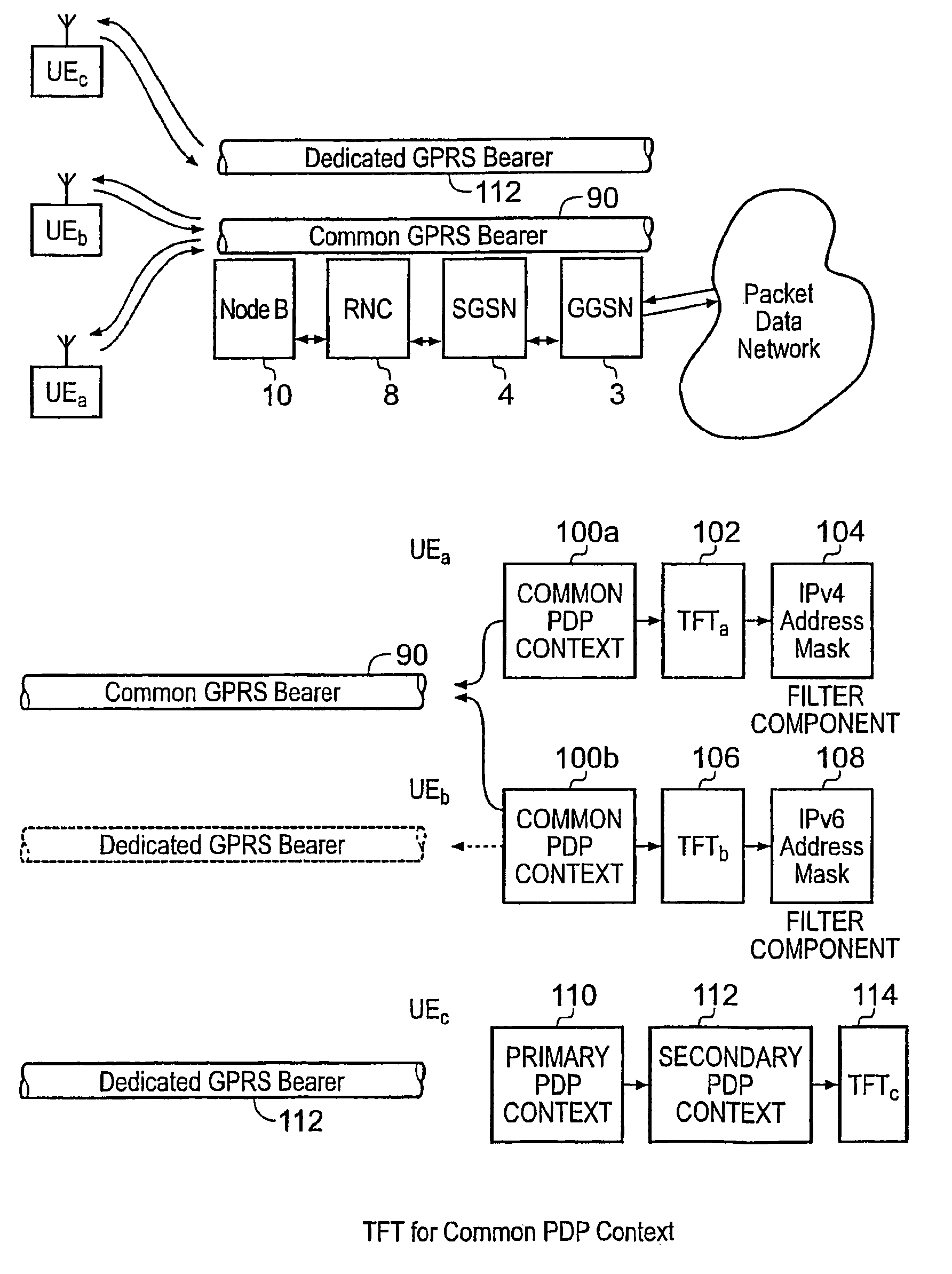
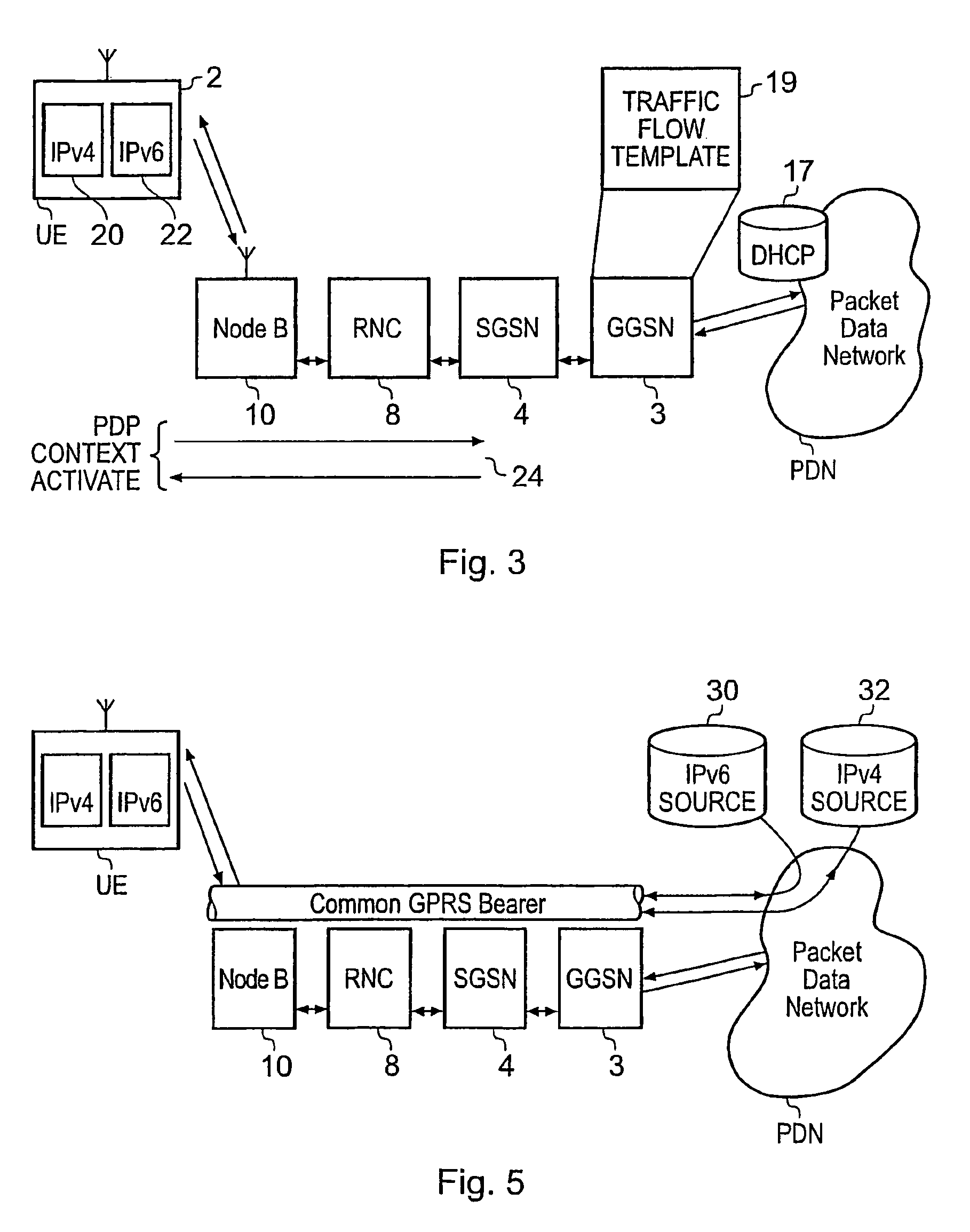
"The present invention provides a packet radio network that can efficiently support internet packets to and from mobile user equipment. The network includes a gateway support node, a serving support node, and a radio network controller. The gateway support node provides a packet data protocol context for controlling internet packets to and from the network, while the serving support node controls communications of the internet packets to and from mobile user equipment. The network can support multiple communication sessions and can efficiently use shared radio resources, such as high-speed radio links, to improve resource utilization. The network also allows for the sharing of a common packet communications bearer, which can be used for multiple communication sessions and can support different internet protocol versions. Overall, the invention provides a more efficient and flexible way to utilize network resources for mobile users."

Problems solved by technology

As a result resources may be utilised less efficiently than could be achieved by sharing the same high-speed / broadband GPRS bearers (e.g. HSDPA / HSUPA being the radio bearers).
As a result resource may be utilised less efficiently than could be achieved by sharing the same high-speed / broadband GPRS bearers (e.g. HSDPA / HSUPA being the radio bearers).

Method used


Image

  • Packet radio network and method
  • Packet radio network and method
  • Packet radio network and method

Examples


Embodiment Construction

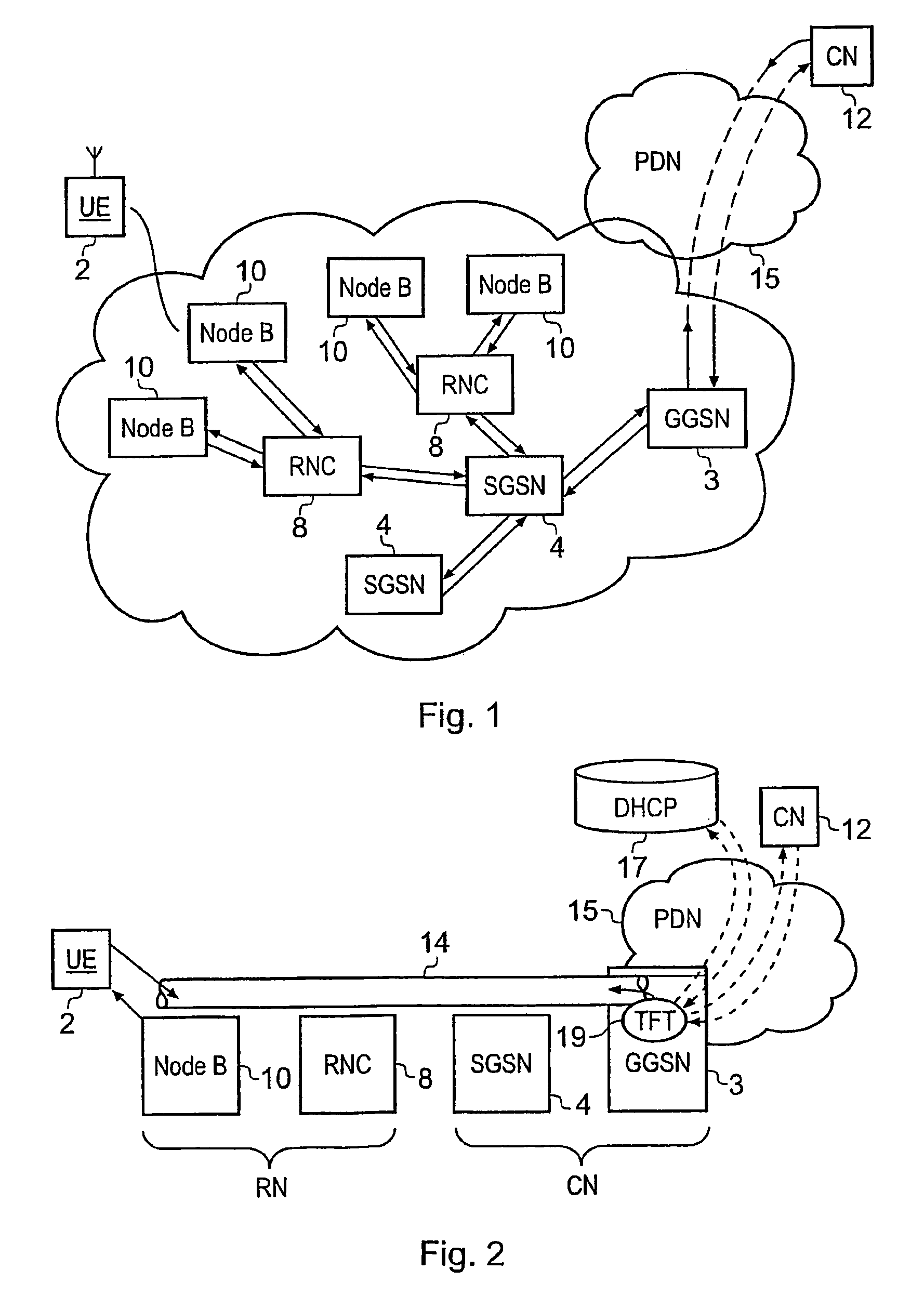
[0037]FIG. 1 provides a schematic block diagram of a GPRS / UMTS packet radio network 1 for communicating internet packets between a mobile user equipment (UE) 2 and a correspondent node (CN) 12, which is attached to an external packet data network 15. In FIG. 1 the UE 2 is arranged to host an application program providing, for example a multimedia service to a user. FIG. 1 shows elements of a GPRS network which are a GPRS gateway service mode (GGSN) 3 a serving GRPS support mode (SGSN) 4 and a radio network controller (RNC) 8. As shown FIG. 2, which provides a simplified representation of the GPRS network shown in FIG. 1, generally the GGSN 3 and the SGSN 4 form parts of a core network, CN, whereas the radio network controller RNC 8 forms part of a radio network RN. As shown in FIG. 2, in a simplified form for the present description, the GPRS network 1 is providing an internet protocol bearer 14 for which a packet data context has been established. As will be explained shortly, a pa...


PUM


Abstract

A packet radio network comprising a gateway support node, a serving support node and a radio network controller provides a facility for communicating internet packets with mobile user equipment. The gateway support node provides a packet data protocol context for controlling communication of internet packets between the packet radio network and mobile user equipment via a packet communications bearer. The serving support node connected to the gateway support node controls communications between the gateway support node and mobile user equipment forming the packet communications bearer. The radio network part provides a radio access bearer for communicating internet packets via a radio access interface with mobile user equipment. In response to a request message, the serving support node with the gateway support node establishes a common packet data protocol context with a packet communications bearer to communicate packets. The common packet communications bearer is shared with another communications session and formed by gateway support node and serving support node using a common tunnelling protocol bearer.

Description

FIELD OF THE INVENTION[0001]The present invention relates to packet radio networks operable to communicate internet protocol packets to and / or from mobile user equipment, such as, for example, a network operating in accordance with the General Packet Radio System (GPRS).BACKGROUND OF THE INVENTION[0002]The GPRS has been developed to communicate internet packets via a radio access interface. A GPRS network can be formed using a Global System for Mobile Communications (GSM) or a Universal Mobile Telecommunications System (UMTS) backbone network. GPRS provides support for packet-orientated services and attempts to optimise network and radio resources for packet data communications such as for example Internet Packets (IP). The GPRS provides a logical architecture, which is related to the circuit switched architecture of a mobile radio system.[0003]In GPRS / UMTS networks, each mobile user equipment needs to set up at least one GPRS / UMTS communications session represented by packet data p...

Claims


Application Information

Patent Timeline
Patent Type & Authority Patents(United States)
IPC IPC(8): H04W4/00H04W76/02H04W80/00
CPCH04W76/022H04W80/00H04W76/12
Inventor CHEN, XIAOBAOLUCAS, PHILIPPEHARRIS, MARTIN BARKLEY
Owner 3G LICENSING SA
Learn More