Method for controlling the power supply from a power source to a power consumer

a power supply and power consumer technology, applied in the direction of liquid/fluent solid measurement, electric variable regulation, instruments, etc., can solve the problems of less perceived intensity, substantial increase in intensity, and no longer available computation time for implementing other tasks, etc., to achieve sufficient computation time, high resolution, and high precision

Inactive Publication Date: 2011-12-06
LEHMANN ERHARD
View PDF11 Cites 5 Cited by
  • Summary
  • Abstract
  • Description
  • Claims
  • Application Information

AI Technical Summary

Benefits of technology

[0020]In a practical embodiment of the method, all blocks in a period have the same length, and all switchover segments within the blocks may have the same length. This identical configuration of the individual blocks is an advantage in terms of the control technology because it reduces the programming complexity for setting certain ON periods as a function of corresponding input values. In particular, the case may occur that a high value of the ON period corresponds exactly to the small ON period value times an integer. If the small value is implementable within a block, then in the case of identical blocks the large value may simply be achieved by identical activation of a number of blocks within a period corresponding to the aforementioned integer.
[0024]In another practical embodiment of the method according to the present invention, multiple manipulated variables are allocated to each setpoint value, these manipulated variables predetermining the switching points in time for each of the blocks of the period. This makes it possible to reduce the data processing complexity because as many blocks as possible of one period are switched in the same way. The manipulated variables may thus contain a simple specification of the switching points in time and an identification of the blocks that are to be switched at these switching points in time.

Problems solved by technology

This is very complicated and is associated with the use of a large amount of computation resources for the particular program control.
Under some circumstances adequate computation time is no longer available on the microcontroller for implementing other tasks.
This means that at a low luminous output, even a very minor increase in power supply results in a substantial increase in intensity.
At a high luminous output, however, increases in power supply result in less perceived intensity.
When a sound source is operated quietly, a minor increase in power supply results in a great increase in loudness.
In a loud environment, however, an increase in power supply results only in a minor increase in loudness.
On the other hand, at a high power, the resolution of the known methods is too high.

Method used


Image

  • Method for controlling the power supply from a power source to a power consumer
  • Method for controlling the power supply from a power source to a power consumer
  • Method for controlling the power supply from a power source to a power consumer

Examples


Embodiment Construction

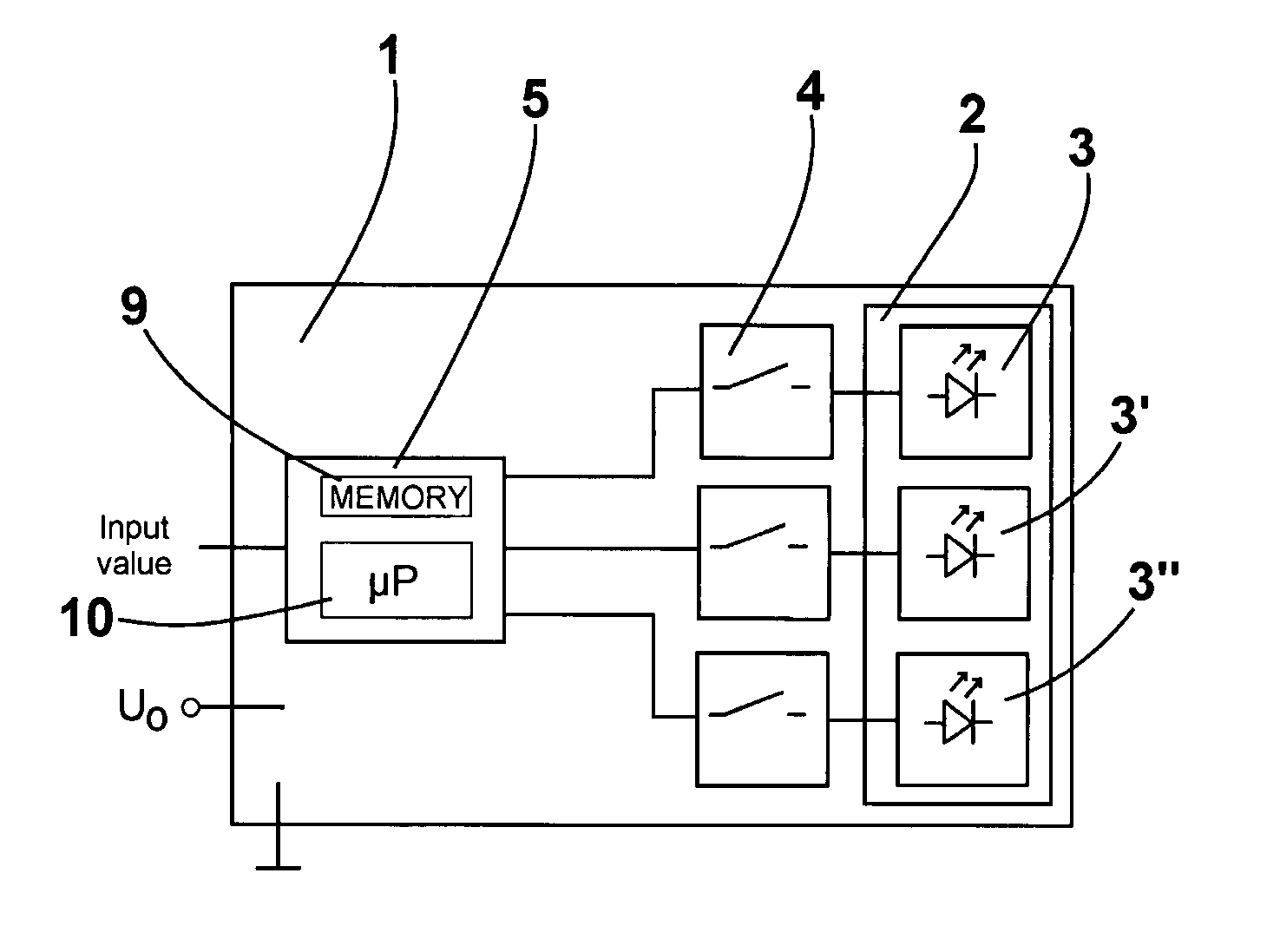
[0036]FIG. 1 schematically shows a block diagram of a light module 2 which is situated on a circuit board 1 and has three LEDs 3, 3′, 3″ of three different colors. Although only one LED 3, 3′, 3″ is shown for each color, a plurality of LEDs 3, 3′, 3″ of the same color may also be provided for each color, situated in such a way that they are interconnected in a parallel circuit.

[0037]Each LED 3, 3′, 3″ shown here emits light of a different wavelength range. First LED 3 may emit green light, second LED 3′ may emit blue light and third LED 3″ may emit red light. By additive color mixing, light module 2 may represent any desired color by adjusting different light intensities of different LEDs 3, 3′, 3″.

[0038]Furthermore, FIG. 1 shows the ground potential and power supply voltage U0, ensuring power supply for three LEDs 3, 3′, 3″. All LEDs 3, 3′, 3″ are connected to one switch 4 each. Each LED 3, 3′, 3″ may receive power via switch 4 or may be isolated from the power supply independently...


PUM


Abstract

A system and method for controlling power supply of a power source to at least one power consumer to a desired value in the range of from 0 and 100% in which the operating time of the power consumer is divided up into periods and the power output by the power source is switched on within one period only during the duty cycle which is the portion of the period length that corresponds to the desired value. Resolution provided by the present system and method is improved over known techniques for the static division of the period into equally long periods, especially in the control of light modules having low intensities. The present system and method includes the feature in which the period length is divided up into a number of blocks, every block having at least one switch segment in which the switching state can be modified, and at least one static segment in which the switching state cannot be modified.

Description

TECHNICAL FIELD[0001]The present application relates to a method for controlling the power supply from a power source to at least one power consumer.[0002]The present application also relates to a computer program product for controlling the power supply from a power source to a power consumer.BACKGROUND OF THE INVENTION[0003]Numerous methods for controlling the power supply from a power source to a power consumer are known from the related art, where a certain input value is preselected by a control unit. With the digital control units customary today, a binary number is used as the input value, e.g., an 8-bit number which may represent an integer between 0 and 255.[0004]In the method known as pulse width modulation, as described in the white paper of Artistic Licence (UK) Ltd., Great Britain, dated May, 2002, entitled “An overview of the electronic drive techniques for intensity control and colour mixing of low voltage light sources such as LEDs and LEPs”, for example, the operati...

Claims


Application Information

Patent Timeline
Patent Type & Authority Patents(United States)
IPC IPC(8): G06F1/26G06F1/32H05B44/00
CPCH05B33/0818H05B33/0866H05B39/047H05B41/3921Y02B20/346H05B45/32H05B45/24Y02B20/30
Inventor LEHMANN, ERHARD
Owner LEHMANN ERHARD
Why Eureka
Try Eureka