Method of manufacturing thermally assisted magnetic head

a technology of magnetic head and thermally assisted head, which is applied in the field of manufacturing a thermally assisted magnetic head, can solve the problems of difficult core layer and magnetic pole, and achieve the effect of easy control of distan

Active Publication Date: 2011-12-13
TDK CORPARATION
View PDF7 Cites 4 Cited by
  • Summary
  • Abstract
  • Description
  • Claims
  • Application Information

AI Technical Summary

Benefits of technology

[0007]In view of the problem mentioned above, it is an object of the present invention to provide a method of manufacturing a thermally assisted magnetic head which can place the core and the magnetic pole closer to each other and easily control the distance between the core and magnetic pole such as to make it fall within a predetermined range.
[0009]Since the part of the second multilayer body formed on the first multilayer body (also referred to as projected part of the second multilayer body in the following) relatively projects from the part of the second multilayer body formed about the first multilayer body at the time of executing the removing step in the present invention, the projected part of the second multilayer body is easily removed by the removing step. When polishing the projected part of the second multilayer body, the first polishing stop layer in the first multilayer body restrains the core layer from being polished. This makes it easy for the thickness of the second cladding layer on the core layer to become zero without polishing the core layer. Even when forming a number of devices at once, the thickness of each second cladding layer can easily be made zero without polishing the core layers. At the time of polishing, the part of the second cladding layer located about the core layer is covered with the second polishing stop layer and thus can be restrained from being polished unnecessarily, whereby its thickness can easily be kept at a desirable thickness. Therefore, after the removing step, a relatively flat third cladding layer can be formed with a predetermined minute thickness on the core layer and the second cladding layer located thereabout without further polishing steps. Forming a magnetic pole on the third cladding layer can make the distance between the core and magnetic pole shorter. Also, even when the same step is simultaneously performed for a plurality of heads, the distance between the core and magnetic pole can be controlled so as to fall within a predetermined range among the plurality of heads.
[0011]This allows the lower face of the second polishing stop layer to have a height not lower than the upper face of the second polishing stop layer, whereby the second polishing stop layer also restrains the core layer from being polished.
[0013]This makes it easy to flatten the surface of the third cladding layer without polishing.
[0014]The present invention provides a method of manufacturing a thermally assisted magnetic head which can place the core and the magnetic pole closer to each other and easily control the distance between the core and magnetic pole such as to make it fall within a predetermined range.

Problems solved by technology

However, it is difficult for the core layer and the magnetic pole to be positioned sufficiently close to each other when the cladding layer surrounding the core layer is formed and flattened while the electromagnetic coil device is simply formed on the flattened surface of the cladding layer as conventionally done.
This is because the polishing of the cladding layer on the core layer is hard to stop immediately in front of the core layer, whereby there are fears of the core layer being polished when attempting to make the cladding layer sufficiently thin on the core layer, and the thickness of the cladding layer, i.e., the distance between the core layer and magnetic pole, fluctuating greatly among the devices.

Method used


Image

  • Method of manufacturing thermally assisted magnetic head
  • Method of manufacturing thermally assisted magnetic head
  • Method of manufacturing thermally assisted magnetic head

Examples


Embodiment Construction

[0024]Modes for carrying out the present invention will now be explained in detail with reference to the accompanying drawings. In the drawings, the same elements are referred to with the same numerals. For easier viewing of the drawings, ratios of sizes within and between constituents therein are arbitrary.

[0025]Hard Disk Drive

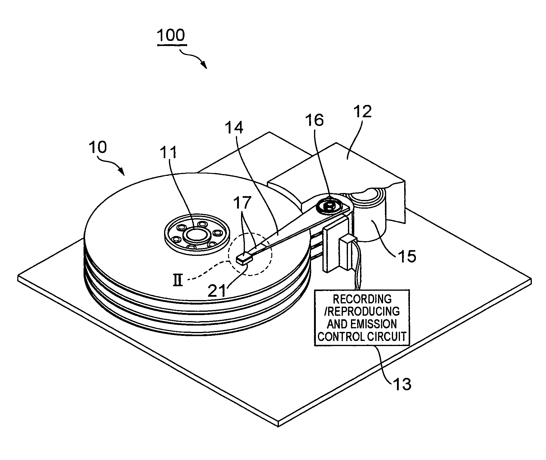
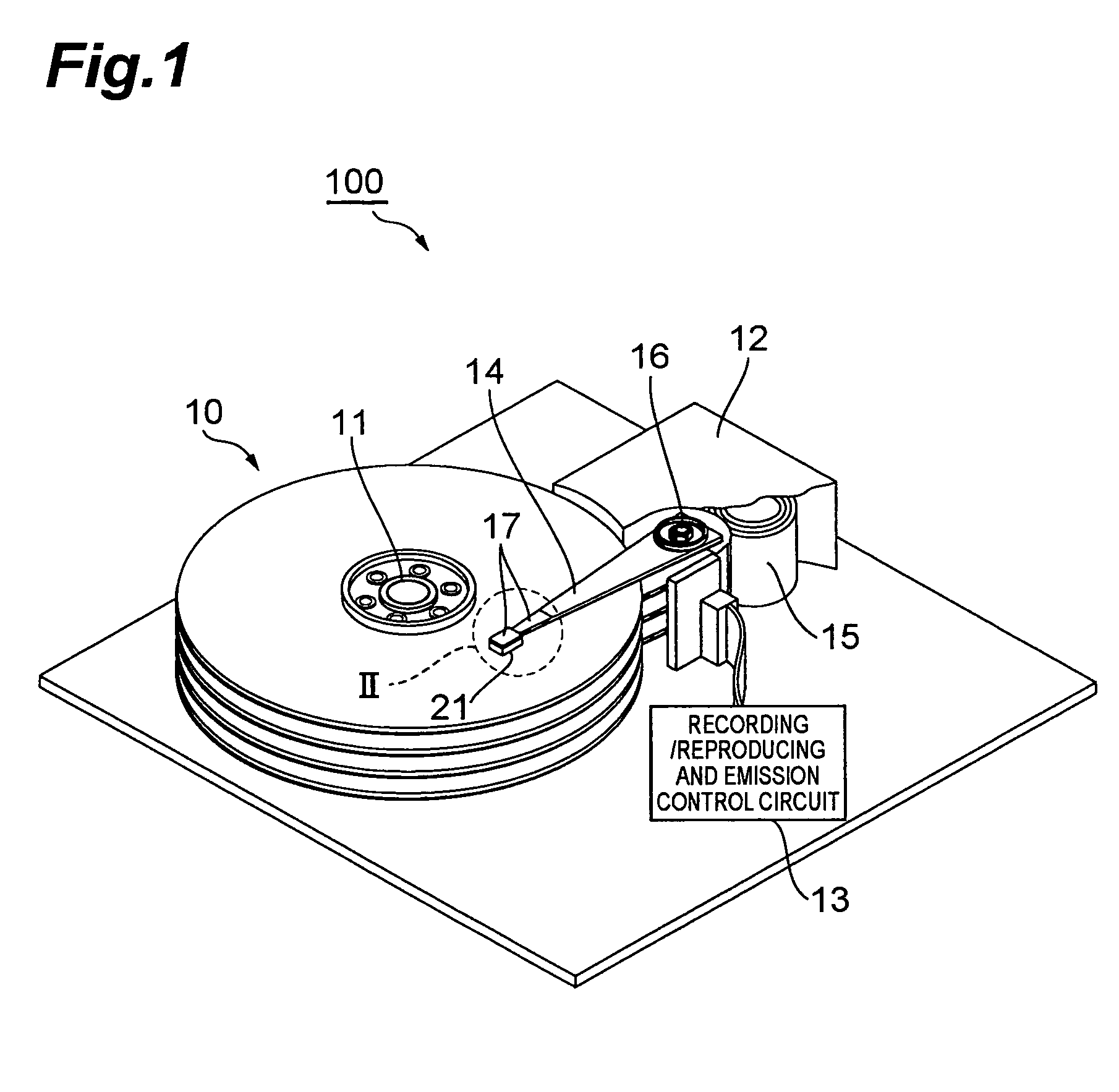
[0026]FIG. 1 is a perspective view of a hard disk drive in accordance with an embodiment.

[0027]This hard disk drive 1 comprises magnetic disks which are a plurality of magnetic recording media rotating about a rotary shaft of a spindle motor 11, an assembly carriage device 12 for positioning a thermally assisted magnetic head 21 on a track, and a read / write control circuit 13 for controlling writing and reading actions of the thermally assisted magnetic head 21 and regulating a laser diode acting as a light source for generating laser light for thermally assisted magnetic recording which will later be explained in detail.

[0028]The assembly cage device 12 is p...


PUM

PropertyMeasurementUnit
thicknessaaaaaaaaaa
thicknessaaaaaaaaaa
thicknessaaaaaaaaaa

Abstract

A method comprises a first multilayer body forming step of forming a first multilayer body on a first cladding layer, the first multilayer body including a core layer and a first polishing stop layer in order from the first cladding layer side; a first multilayer body patterning step of pattering the first multilayer body, so as to expose the first cladding layer about the patterned first multilayer body; a second multilayer body forming step of forming a second multilayer body on the exposed first cladding layer and patterned first multilayer body, the second multilayer body including a second cladding layer and a second polishing stop layer in order from the first cladding layer side; and a removing step of polishing away a part of the second multilayer body formed on the first multilayer body.

Description

BACKGROUND OF THE INVENTION[0001]1. Field of the Invention[0002]The present invention relates to a method of manufacturing a thermally assisted magnetic head which enables high-density recording.[0003]2. Related Background Art[0004]As a means for achieving higher recording density in hard disk drives, a so-called thermally assisted magnetic recording scheme has been proposed, which uses a magnetic material having large KU as a recording medium, while heat is applied to the recording medium immediately before exerting a writing magnetic field, so as to effect writing with a lower coercivity.[0005]Known as a thermally assisted magnetic head used in such a thermally assisted magnetic recording scheme is one in which a core layer and a cladding layer surrounding the core layer are provided within a slider, an electromagnetic coil device is laminated on the cladding layer, and a plasmon probe is provided on a medium-opposing surface of the core layer as in Japanese Patent Application Lai...

Claims


Application Information

Patent Timeline
Patent Type & Authority Patents(United States)
IPC IPC(8): H01L21/64
CPCG11B5/314G11B5/3163G11B2005/0021
Inventor TANAKA, KOSUKESHIMAZAWA, KOJI
Owner TDK CORPARATION
Why Eureka
Try Eureka