Exhaust gas recirculation cooler and method

a technology of exhaust gas and cooler, which is applied in the direction of combustion air/fuel air treatment, machines/engines, lighting and heating apparatus, etc., can solve the problems of short time allowed for heat exchange therebetween, ineffective heat transfer to the cooling water that moves around the exhaust gas and the tubes, and large quantities of exhaust gas of automobiles. achieve the effect of effective heat transfer between cooling fluid and gas

Inactive Publication Date: 2011-12-20
MODINE MFG CO
View PDF14 Cites 8 Cited by
  • Summary
  • Abstract
  • Description
  • Claims
  • Application Information

AI Technical Summary

Benefits of technology

[0006]Some embodiments of the present invention relate to EGR coolers, and specifically, with EGR coolers in which an inlet / outlet tube is installed by insertion such that a curved gas flow path may be formed on a tank body into which cooling fluid enters, and subsequently, heat transfer between cooling fluid and gas takes place effectively.
[0007]In some embodiments, an EGR cooler is provided that promotes effective heat transfer between gas and cooling fluid, thereby increasing heat exchange efficiencies. The EGR cooler can also promote smooth flow of the gas introduced, and can prevent accumulation of impurities contained in the gas.

Problems solved by technology

In general, the exhaust gas of an automobile contains large quantities of harmful substances including carbon monoxides, nitrogen oxides, and hydrocarbons.
However, as exhaust gas undergoes horizontal movement through straight tubes in EGR coolers according to the prior art, effective contact between the tubes and cooling water often does not take place, and the time allowed for heat exchange therebetween becomes short.
Consequently, heat transfer to the cooling water that moves around the exhaust gas and the tubes often does not take place effectively.
As a result, heat exchange efficiency can suffer remarkably.
In addition, in the event that the flow of exhaust gas becomes weak in the tubes, soot and other material in the exhaust gas can accumulate in flow pathways, thereby interfering with the flow of exhaust gas.
Furthermore, existing straight EGR coolers can restrict positioning and installation of other parts in a vehicle, where space is typically at a premium.
Such restrictions can negatively impact the efficient and effective positioning and installation of parts within a vehicle.

Method used


Image

  • Exhaust gas recirculation cooler and method
  • Exhaust gas recirculation cooler and method
  • Exhaust gas recirculation cooler and method

Examples


Embodiment Construction

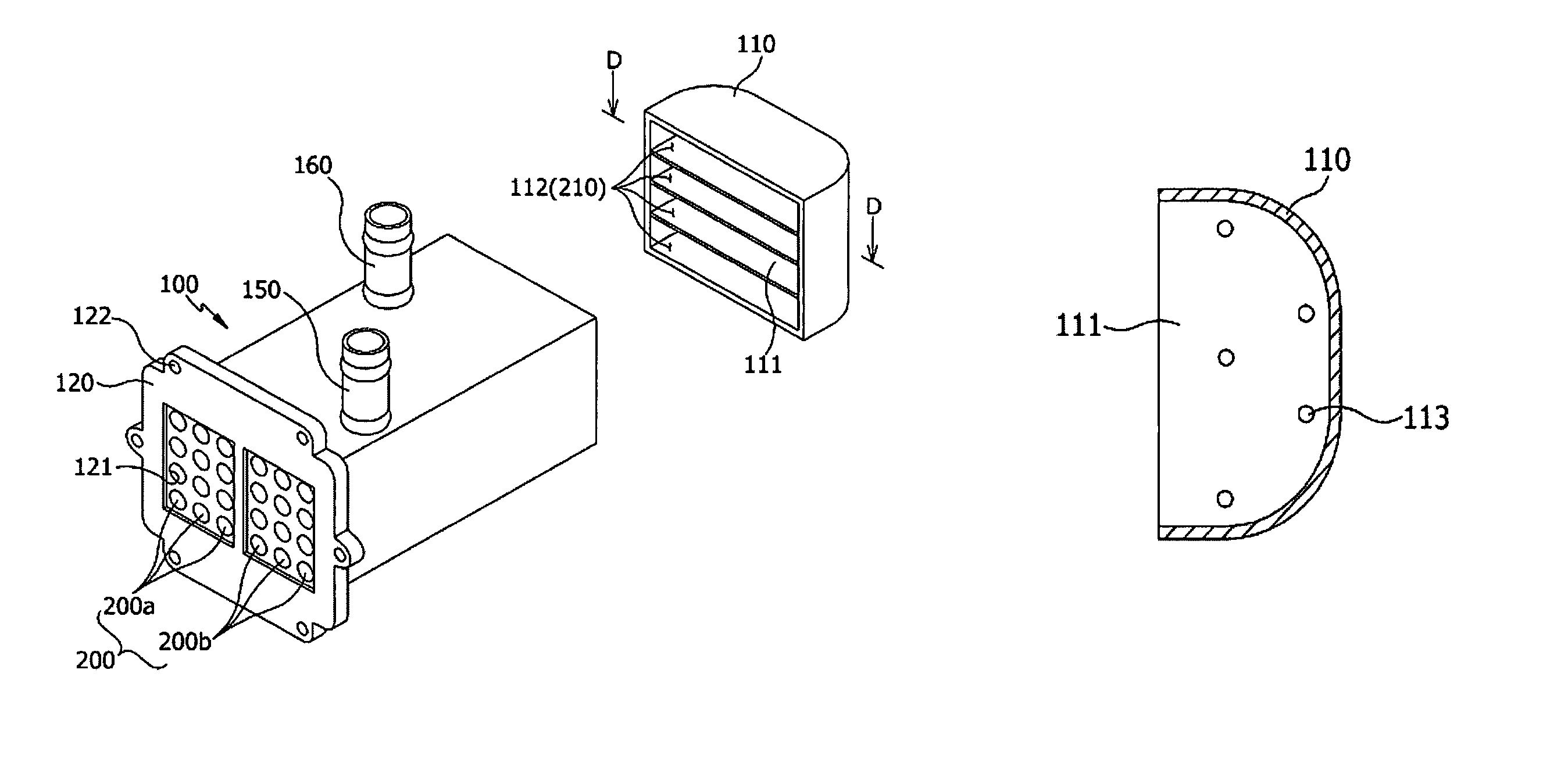
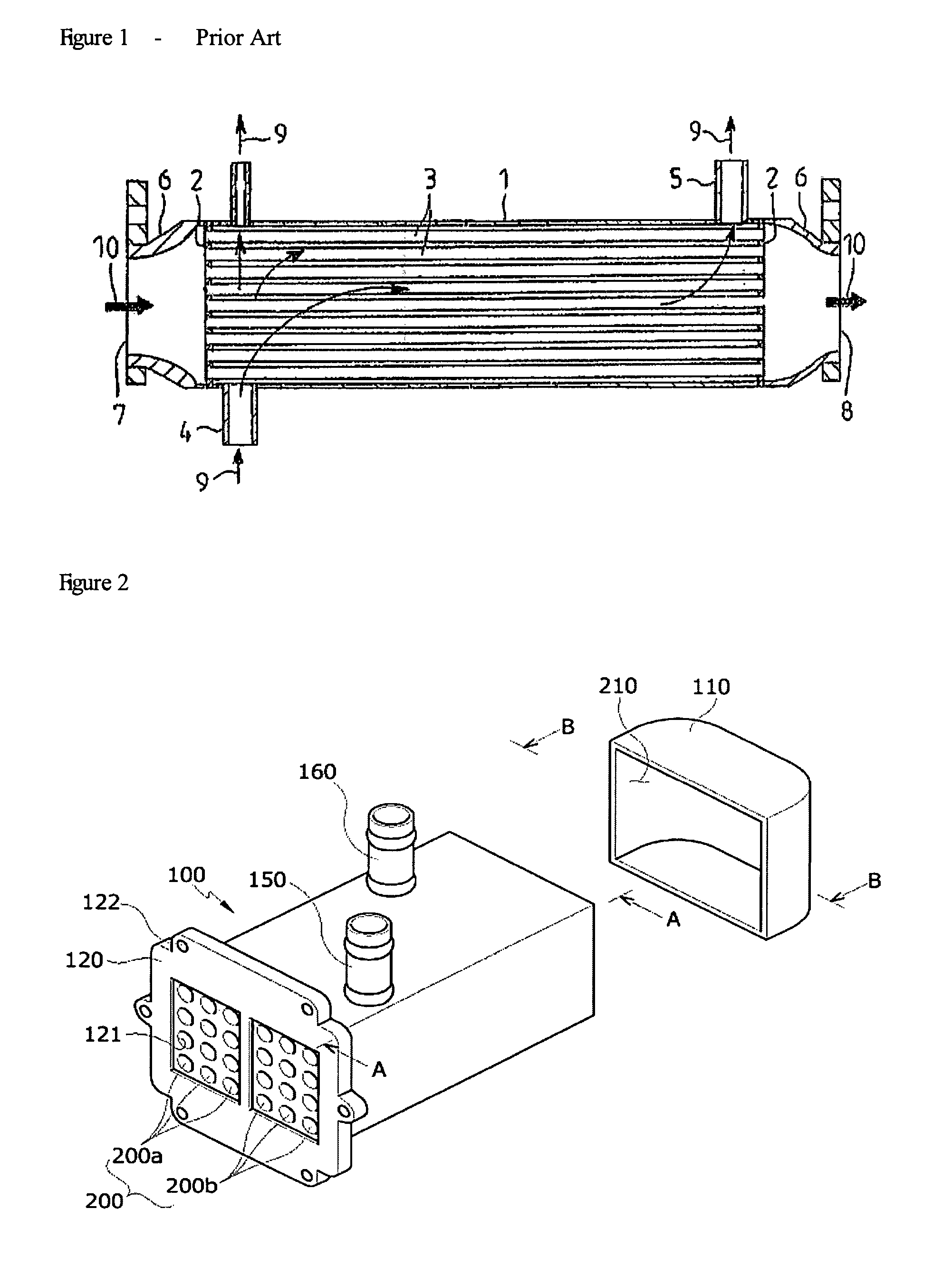
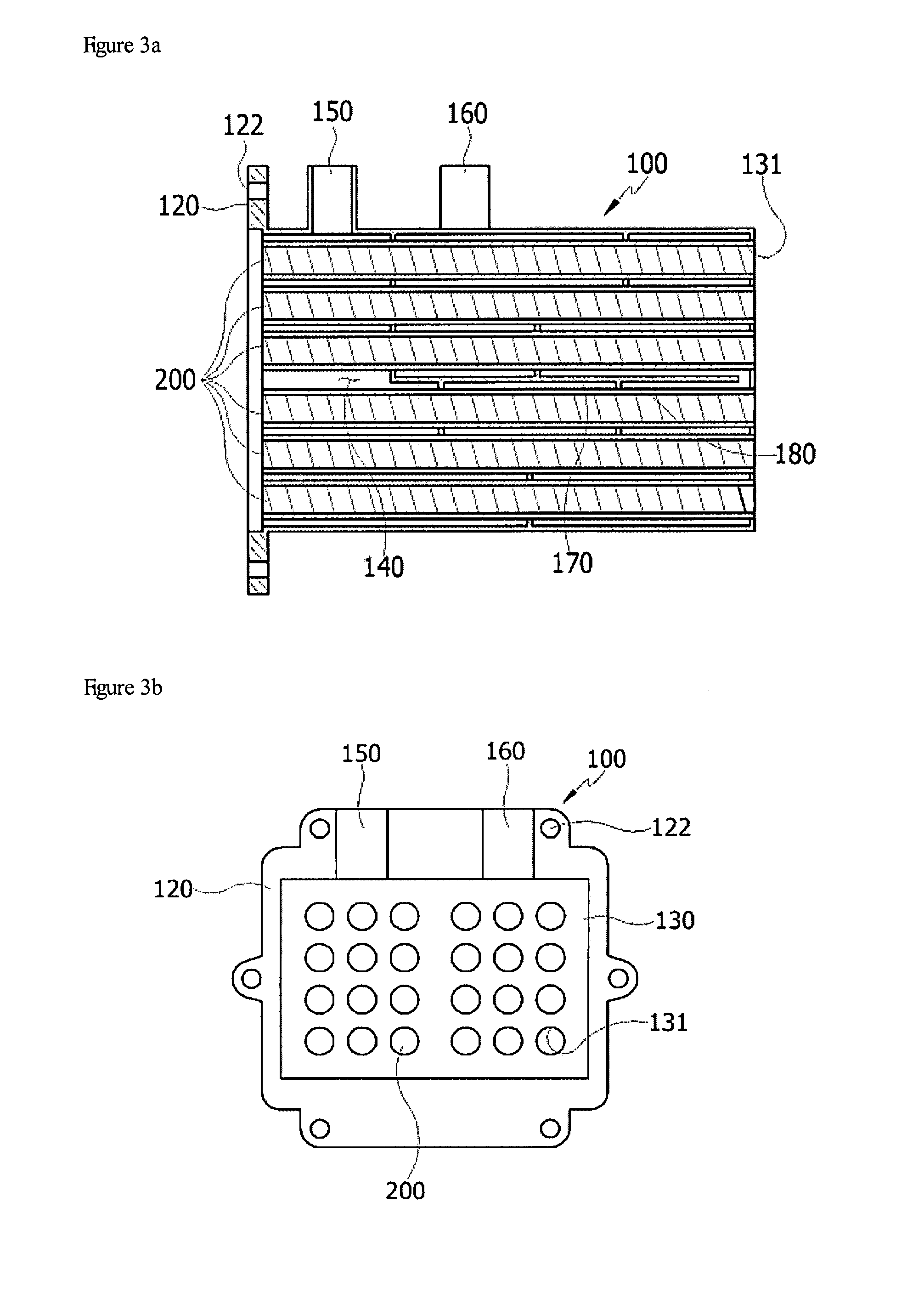
[0022]Some embodiments of present invention provide an EGR cooler comprising a tank body through which cooling fluid enters and exits, and an inlet / outlet tube installed by insertion so that a curved gas flow path can be formed. In some embodiments, the inlet / outlet tube includes a first inlet / outlet tube and a second inlet / outlet tube to introduce and discharge gas. A connection housing can be installed on the tank body so as to interface individual ends of the first inlet / outlet tube and the second inlet / outlet tube with one another.

[0023]In some embodiments, it is preferred that an inner side of the connection housing comprises a rounded face to form a “U”-shaped gas flow path in the EGR cooler, a plurality of chambers formed in the connection housing and partitioned by one or more plates, and gas interface holes formed on one or more of the plates so that the chambers can be interfaced with one another.

[0024]In addition, a separator wall is installed in the tank body to form a c...


PUM


Abstract

An EGR cooler having an inlet / outlet tube installed by insertion is provided, and can have a curved gas flow path defined at least in part by a tank body. The inlet / outlet tube can include a first inlet / outlet tube and a second inlet / outlet tube to introduce and to exhaust gas. The tank body can have a configuration such that a connection housing is installed to establish fluid communication between individual ends of both the first inlet / outlet tube and second inlet / outlet tube, so that heat exchange efficiency between the inflow gas and the cooling fluid can be improved, and effective space utilization can be promoted in equipping an vehicle with the EGR cooler.

Description

CROSS-REFERENCE TO RELATED APPLICATIONS[0001]Priority is hereby claimed to Korean Patent App. No. KR 2006-061857 filed on Jul. 3, 2006, the entire contents of which are incorporated herein by reference.BACKGROUND[0002]In general, the exhaust gas of an automobile contains large quantities of harmful substances including carbon monoxides, nitrogen oxides, and hydrocarbons. While the production of harmful substances such as nitrogen oxides often increases in quantity with the temperature of an engine, EGR (Exhaust Gas Recirculation) is used to decrease such harmful substances by recirculating exhaust gas into an intake system and lowering the combustion temperature in a cylinder. In many EGR processes, an EGR cooler is installed that is intended to cool high-temperature exhaust gas with cooling water.[0003]FIG. 1 is a vertical cross-sectional view illustrating an EGR cooler according to the prior art. As illustrated in FIG. 1, the EGR cooler is comprised of a cylindrical cell 1, plates...

Claims


Application Information

Patent Timeline
Patent Type & Authority Patents(United States)
IPC IPC(8): F28F9/22
CPCF02M25/0737F02M25/0701Y02T10/121F02M26/32F02M26/50
Inventor KIM, ILHWAN
Owner MODINE MFG CO
Why Eureka
Try Eureka