Planar monopole antenna and electronic device
a technology of electronic devices and monopole antennas, applied in the direction of radiating element structural forms, elongated active element feeds, resonance antennas, etc., can solve the problems of difficult to attach components to film antennas, difficult to obtain impedance matching properly, and large size and an area of antennas, etc., to achieve the effect of convenient manufactur
- Summary
- Abstract
- Description
- Claims
- Application Information
AI Technical Summary
Benefits of technology
Problems solved by technology
Method used
Image
Examples
first modification
(First Modification)
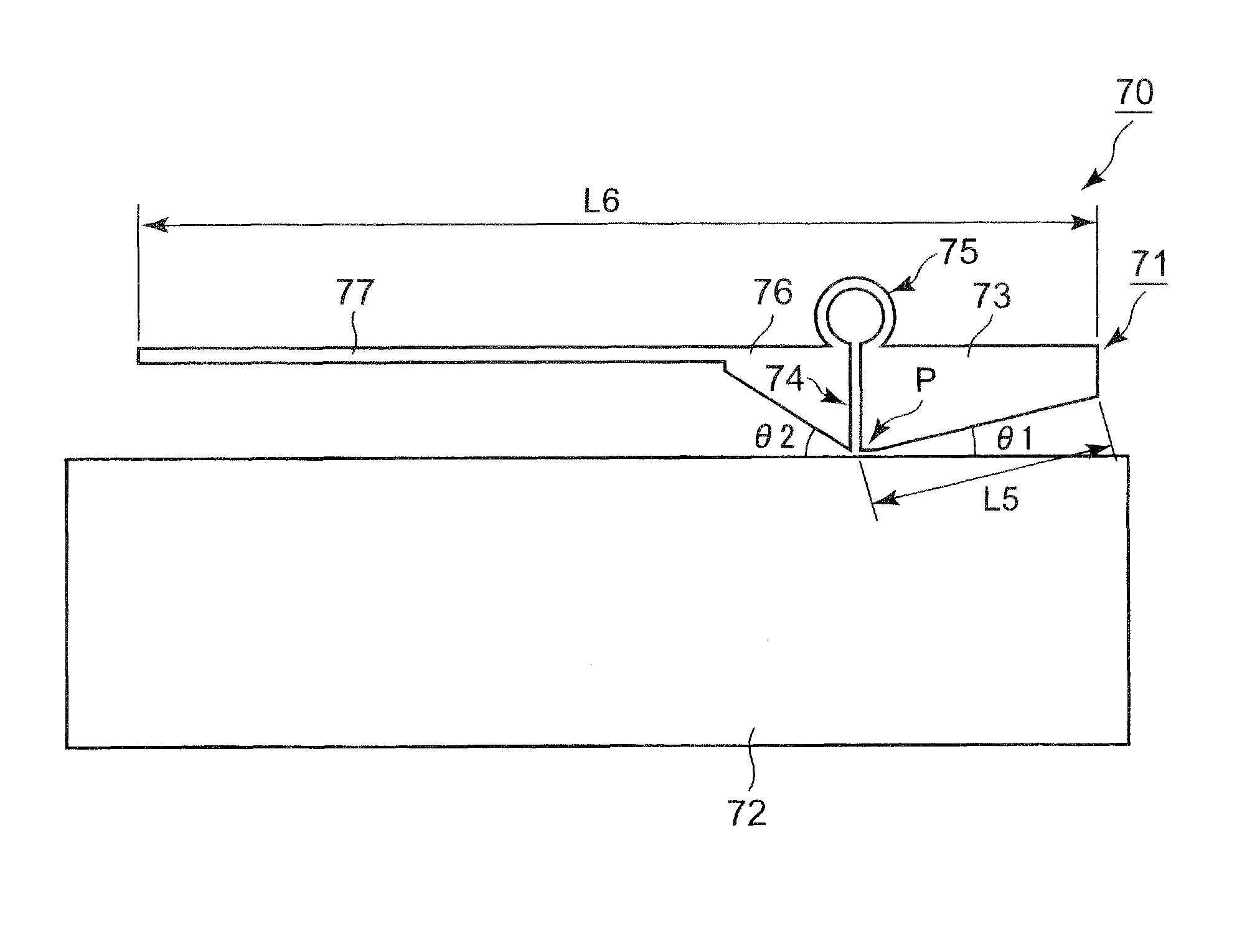
[0093]A firs modification of the above-described embodiment will be described with reference to FIG. 11. FIG. 11 shows a configuration of a planar monopole antenna 70.
[0094]In the first modification, the planar monopole antenna 70 is provided in the handy terminal 1 of the above-described embodiment in place of the planar monopole antenna 30. As shown in FIG. 11, the planar monopole antenna 70 includes the film 31 (which is omitted in FIG. 11) formed of an insulating material such as polyimide, and a monopole section 71 and a ground section 72, each of which is formed of a conductive material such as copper foil and formed on the film 31. In the monopole section 71, a trapezoidal pole section 73, a coil section 75, a trapezoidal pole section 76, and a strip-shaped pole section 77 are formed in this order in an integrated manner.
[0095]A capacitor section 74 is formed by a combination of the pole section 73 and pole section 76 so as to have a gap therebetween. A fe...
second modification
(Second Modification)
[0103]A second modification of the above-described embodiment will be described with reference to FIG. 12. FIG. 12 shows a configuration of a planar monopole antenna 30b.
[0104]In the second modification, the planar monopole antenna 30b is provided in the handy terminal 1 according to the above-described embodiment in place of the planar monopole antenna 30. As shown in FIG. 12, the planar monopole antenna 30b includes the film 31 (which is omitted in FIG. 12) formed of an insulating material such as polyimide, and a monopole section 33b and the ground section 32, each of which is formed of a conductive material such as copper foil and formed on the film 31. In the monopole section 33b, a trapezoidal pole section 34b, the capacitor section 35, the coil section 36 and the pole section 37 are formed in this order in an integrated manner. An upper side of the pole section 34b is provided in parallel to the upper side of the ground section 32.
[0105]According to the ...
third modification
(Third Modification)
[0106]A third modification of the above-described embodiment will be described with reference to FIGS. 13A and 13B.
[0107]FIG. 13A shows a configuration of a planar monopole antenna 80. FIG. 13B shows a configuration of a planar monopole antenna 80a.
[0108]In this modification, the planar monopole antenna 80 is provided in place of the planar monopole antenna 30 in the handy terminal 1 of the above-described embodiment. As shown in FIG. 13A, the planar monopole antenna 80 includes the film 31 (which is omitted in FIG. 13A) formed of an insulating material such as polyimide, and a monopole section 81 and a ground section 82, each of which is formed of a conductive material such as copper foil and formed on the film 31. In the monopole section 81, a strip-shaped pole section 83, a coil section 85 and a strip-shaped pole section 86 are formed in this order in an integrated manner.
[0109]A capacitor section 84 is formed by a combination of the pole section 83 and the p...
PUM
 Abstract
Description
Claims
Application Information
 - R&D
- Intellectual Property
- Life Sciences
- Materials
- Tech Scout
- Unparalleled Data Quality
- Higher Quality Content
- 60% Fewer Hallucinations
Browse by: Latest US Patents, China's latest patents, Technical Efficacy Thesaurus, Application Domain, Technology Topic, Popular Technical Reports.
© 2025 PatSnap. All rights reserved.Legal|Privacy policy|Modern Slavery Act Transparency Statement|Sitemap|About US| Contact US: help@patsnap.com


