Compact and stand-alone combined multi-axial and shear test apparatus

a multi-axial and shear-type testing and test apparatus technology, which is applied in the direction of mechanical measurement arrangements, instruments, and mechanical means, can solve the problems of two or more loading devices, complex microstructures of composite materials that can produce complex mechanical responses, and the inability to design reliable structures by structural analysis. the effect of cos

Active Publication Date: 2011-12-27
THE UNITED STATES OF AMERICA AS REPRESENTED BY THE SECRETARY OF THE NAVY
View PDF13 Cites 41 Cited by
  • Summary
  • Abstract
  • Description
  • Claims
  • Application Information

AI Technical Summary

Benefits of technology

It is therefore a general purpose and primary object of the present invention to provide a compact, low cost and stand-alone material testing apparatus that is capable of applying combined multi-axial t

Problems solved by technology

Although these technologies have been known in the art for many years, the technologies have not been refined to a level that reliable structures can be designed by structural analysis.
However, this class of composite material has complex microstructures that can produce complex mechanical responses.
A disadvantage of these methods is the need for two or more loading devices and the relatively high cost of the equipment.
The disadvantage of this apparatus is that the apparatus is not capable of applying in-plane shear to the test specimen.
Another disadvantage of this apparatus is that the biaxial loading is limited to an orthogonal configuration.
The device does not enable the application of multi-axial tension/compression forces in optional combination with in-plane shear forces.
T

Method used


Image

  • Compact and stand-alone combined multi-axial and shear test apparatus
  • Compact and stand-alone combined multi-axial and shear test apparatus
  • Compact and stand-alone combined multi-axial and shear test apparatus

Examples


Embodiment Construction

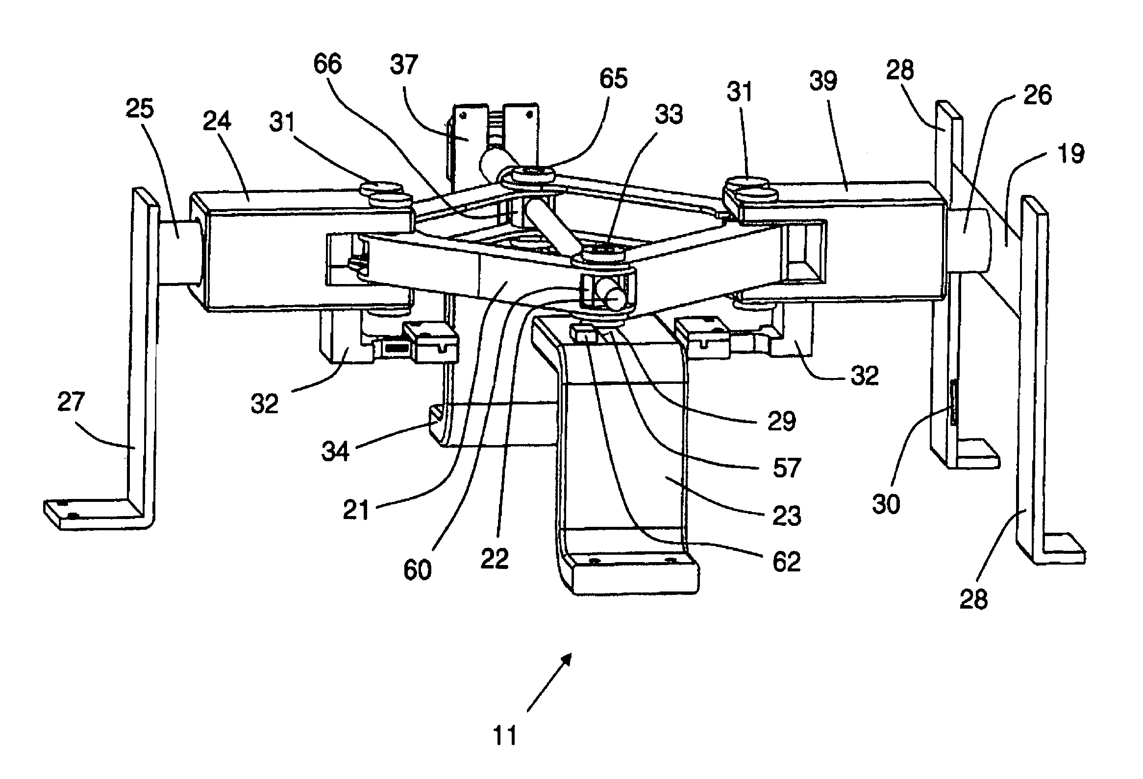
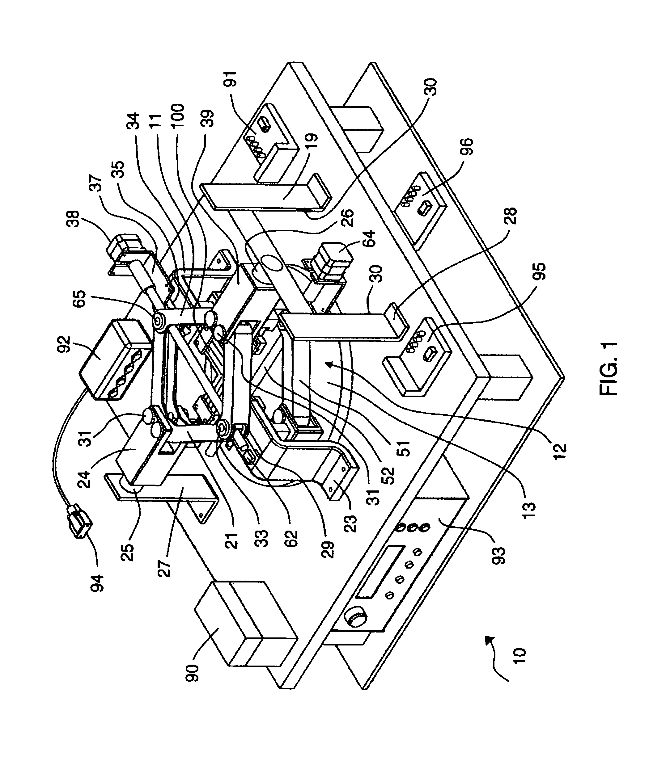
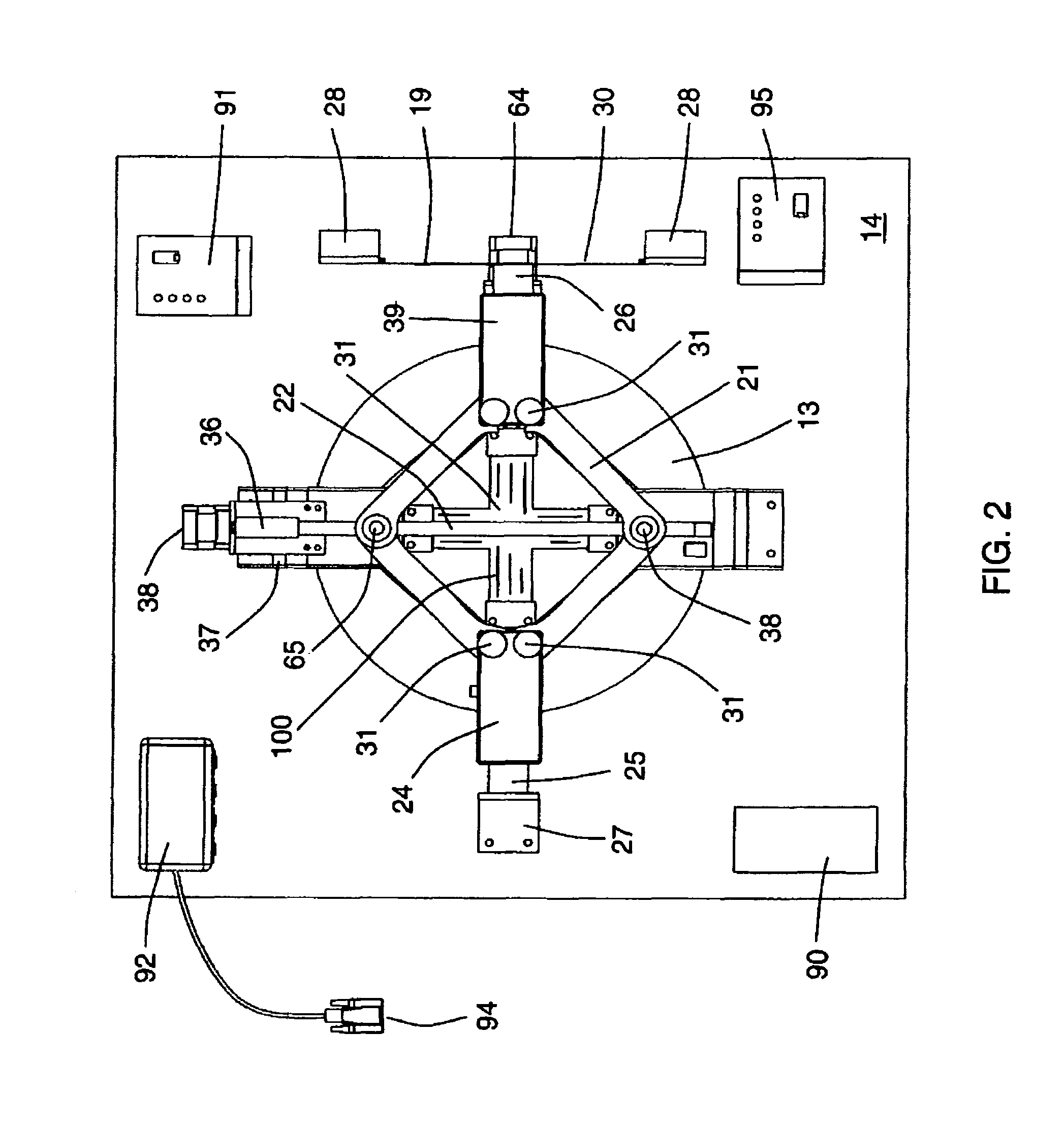
Referring now to FIGS. 1-3, a compact testing apparatus 10 is shown in which the apparatus comprises an upper scissor jack assembly 11, a lower scissor jack assembly 12, a turntable 13 and a support base 14 (preferably sized for tabletop use). For testing, a test specimen 100 is positioned within the apparatus 10.

The upper scissor jack assembly 11 comprises a four-bar linkage 21, hinged in a rhombus shape (similar to an automotive scissor jack) and a power (lead) screw-gear 22. The four hinges of the upper jack assembly 11 are supported by upper assembly support brackets 23, 27, 28 and 34 in which the support brackets are rigidly connected to the fixed base 14.

The screw-gear 22 is activated by a first stepper motor 38 that is controllable by a computer (not shown) thru an electronic driver 91, a data acquisition board 92 and a serial port 94.

The lower scissor jack assembly 12, similar to the upper scissor jack assembly 11, comprises a four bar linkage 51 hinged in a rhombus shape an...


PUM


Abstract

A testing apparatus is disclosed that includes a turntable, an upper scissor jack assembly and a lower scissor jack assembly positioned in parallel planes, about a longitudinal axis and affixed to a base. The apparatus is powered by at least three motors with supporting controllers. The lower assembly is affixed to the base mechanically via the turntable which allows the lower assembly to rotate with respect to the upper assembly. There are two loading plates attached to the hinges of each scissor jack. The test specimen is secured by the loading plate. Each scissor jack operates by a screw-gear powered by one of the motors. Upon energizing a stepper motor; the screw-gear positions a scissor jack to apply a tension or compression on the specimen. While subjected to tension or compression, the lower jack assembly can be rotated with respect to the upper assembly for in-plane shear loading.

Description

CROSS REFERENCE TO OTHER PATENT APPLICATIONSNone.BACKGROUND OF THE INVENTION(1) Field of the InventionThe present invention relates generally to a compact, stand-alone in-plane shear loading and biaxial tension or compression testing apparatus employable for studies of the mechanical properties of materials such as metals, plastics and composites.(2) Description of the Prior ArtFabrics typically used in air-inflated structures (air beams, temporary shelters, tents, temporary bridges, and space structures) are often manufactured in woven or braided forms. These structures rely on inflation pressure to pre-tension the fabric (or membrane) so that the necessary planar stiffness can be developed to achieve rigidity and resistance to in-plane and lateral loads.Unlike metallic structures, air-inflated structures are designed to be lightweight; to have deployed-to-stowed volume ratios that can be in the range of 1000-to-1; and possibly be self-erecting. Although these technologies have bee...

Claims


Application Information

Patent Timeline
IPC IPC(8): G01N3/02
CPCG01N3/08G01N2203/0025G01N2203/0254G01N2203/0282
Inventor SADEGH, ALI M.CAVALLARO, PAUL V.QUIGLEY, CLAUDIA J.
Owner THE UNITED STATES OF AMERICA AS REPRESENTED BY THE SECRETARY OF THE NAVY
Why Eureka
Try Eureka