Solid state relay

a solid-state relay and relay technology, applied in the direction of contact mechanism, switch power arrangement, pulse technique, etc., can solve the problems of slow transformers, cross-talk problems between light emitters and detectors, and difficulty in integration with solid-state relay switch devices, etc., to achieve very high bandwidth, the effect of very fast on and o

Active Publication Date: 2011-12-27
ANALOG DEVICES INC
View PDF28 Cites 21 Cited by
  • Summary
  • Abstract
  • Description
  • Claims
  • Application Information

AI Technical Summary

Benefits of technology

[0007]It is a further object of this invention to provide such an improved solid state relay which can operate a very high bandwidths and the relay can be turned on and off very quickly.

Problems solved by technology

They are slow and they are difficult to integrate with the solid state relay switch devices in the fabrication process for integrated circuit chips.
Further multi-channel designs introduce a cross talk problem between the light emitters and detectors.
One problem with this is that a triac is generally implemented as a discrete element because it is difficult to fabricate in an integrated circuit chip process e.g. CMOS.
In addition these transformers tend to be slow: not able to switch on and off quickly because of their size and higher inductance.
Triacs also have a relatively high forward resistance which makes them less than ideal for low voltage, high current loads.

Method used


Image

  • Solid state relay
  • Solid state relay
  • Solid state relay

Examples


Embodiment Construction

[0022]Aside from the preferred embodiment or embodiments disclosed below, this invention is capable of other embodiments and of being practiced or being carried out in various ways. Thus, it is to be understood that the invention is not limited in its application to the details of construction and the arrangements of components set forth in the following description or illustrated in the drawings. If only one embodiment is described herein, the claims hereof are not to be limited to that embodiment. Moreover, the claims hereof are not to be read restrictively unless there is clear and convincing evidence manifesting a certain exclusion, restriction, or disclaimer.

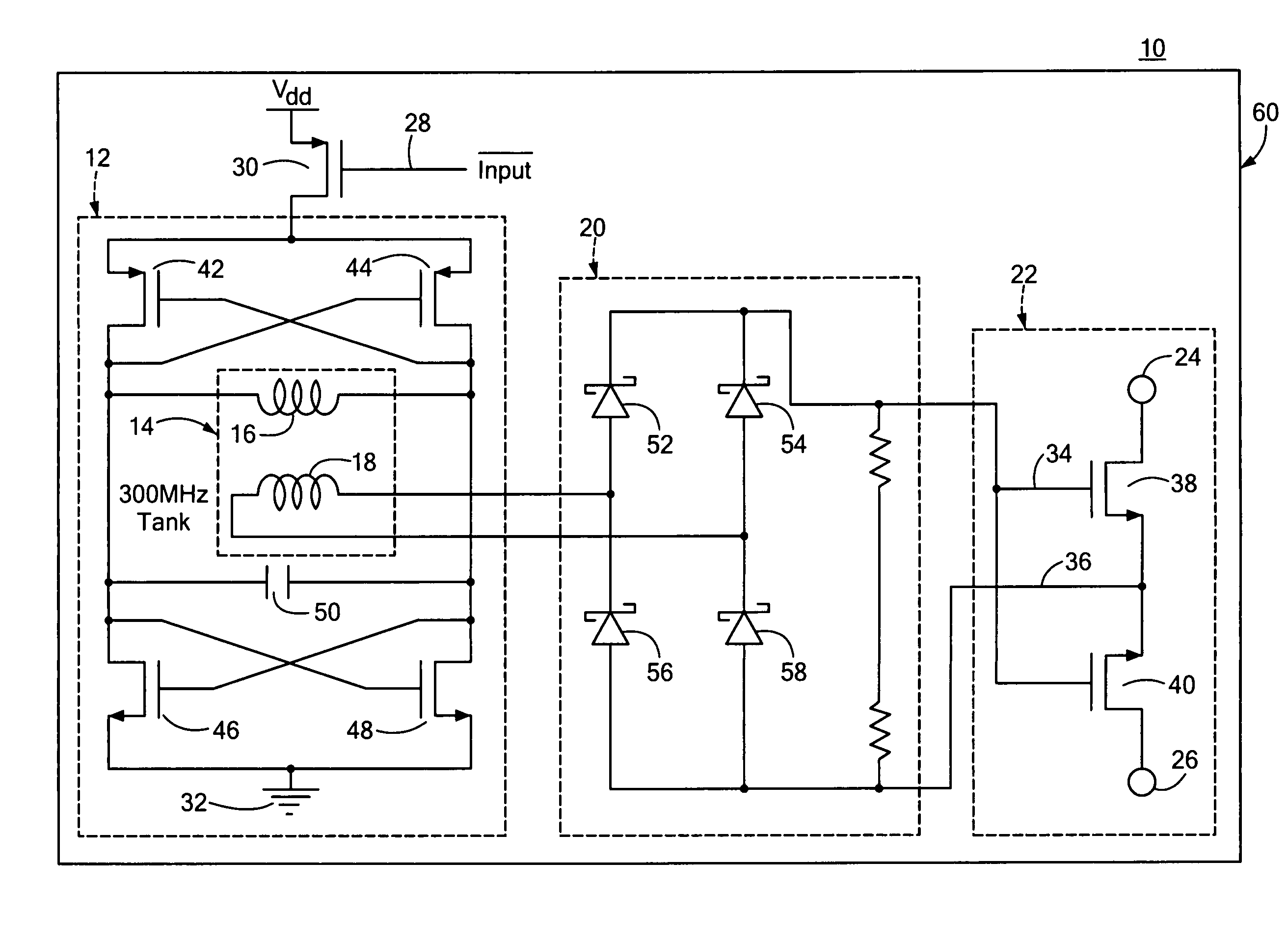
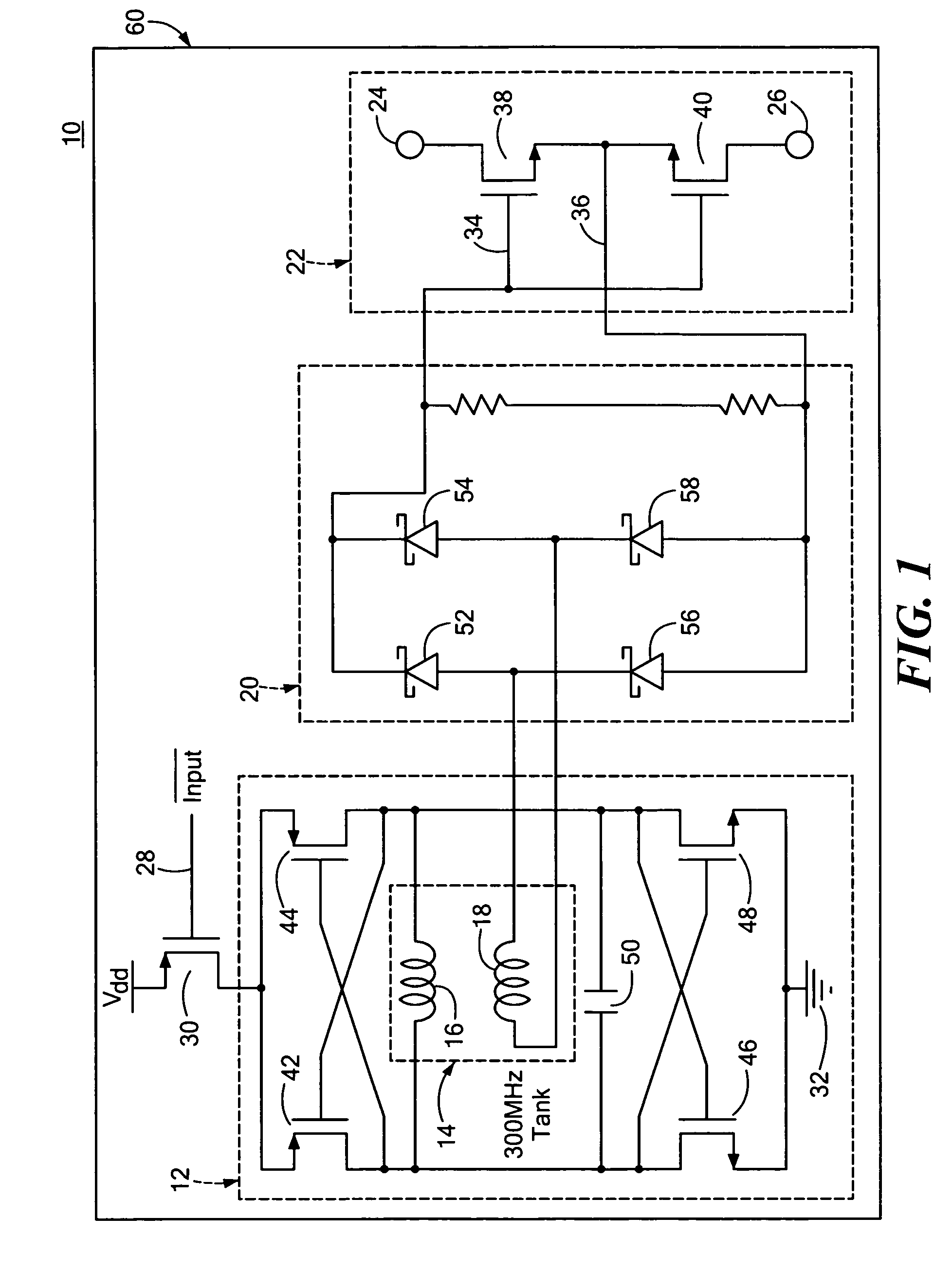
[0023]There is shown in FIG. 1 a solid state relay 10 with transformer isolation including oscillator 12, isolation transformer 14, which includes a primary 16 that actually forms a part of the tank circuit of oscillator 12, and the secondary 18 whose output is connected to rectifier 20. The d.c. output from rectifier 20 dr...


PUM


Abstract

A solid state relay includes: an oscillator circuit responsive to a control signal for generating an a.c. signal; an isolation transformer having a primary winding which forms a part of the tank circuit of the oscillator circuit and a secondary winding; a rectifier responsive to the a.c. signal from the oscillator circuit for providing a d.c. drive signal; and a switch circuit responsive to the drive signal to open and close the relay.

Description

FIELD OF THE INVENTION[0001]This invention relates to an improved solid state relay and more particularly to such a relay which uses an isolation transformer which may be a micro-transformer and which relay may be contained on an integrated circuit chip.BACKGROUND OF THE INVENTION[0002]Solid state relays generally employ an isolation device between the input device or control signal and the relay. One type of isolator is an opto-isolator which uses a light source and a photodiode to isolate the control circuit from the relay. These have a number of shortcomings. They are slow and they are difficult to integrate with the solid state relay switch devices in the fabrication process for integrated circuit chips. Further multi-channel designs introduce a cross talk problem between the light emitters and detectors. Another type of isolator is a transformer isolator that passes the control signal from the primary to the secondary and uses a trigger circuit to respond to a feature e.g. a ri...

Claims


Application Information

Patent Timeline
Patent Type & Authority Patents(United States)
IPC IPC(8): H01H9/54
CPCH03K17/6874H03K17/691H01F17/0006H01F2019/085
Inventor CHEN, BAOXING
Owner ANALOG DEVICES INC
Why Eureka
Try Eureka