

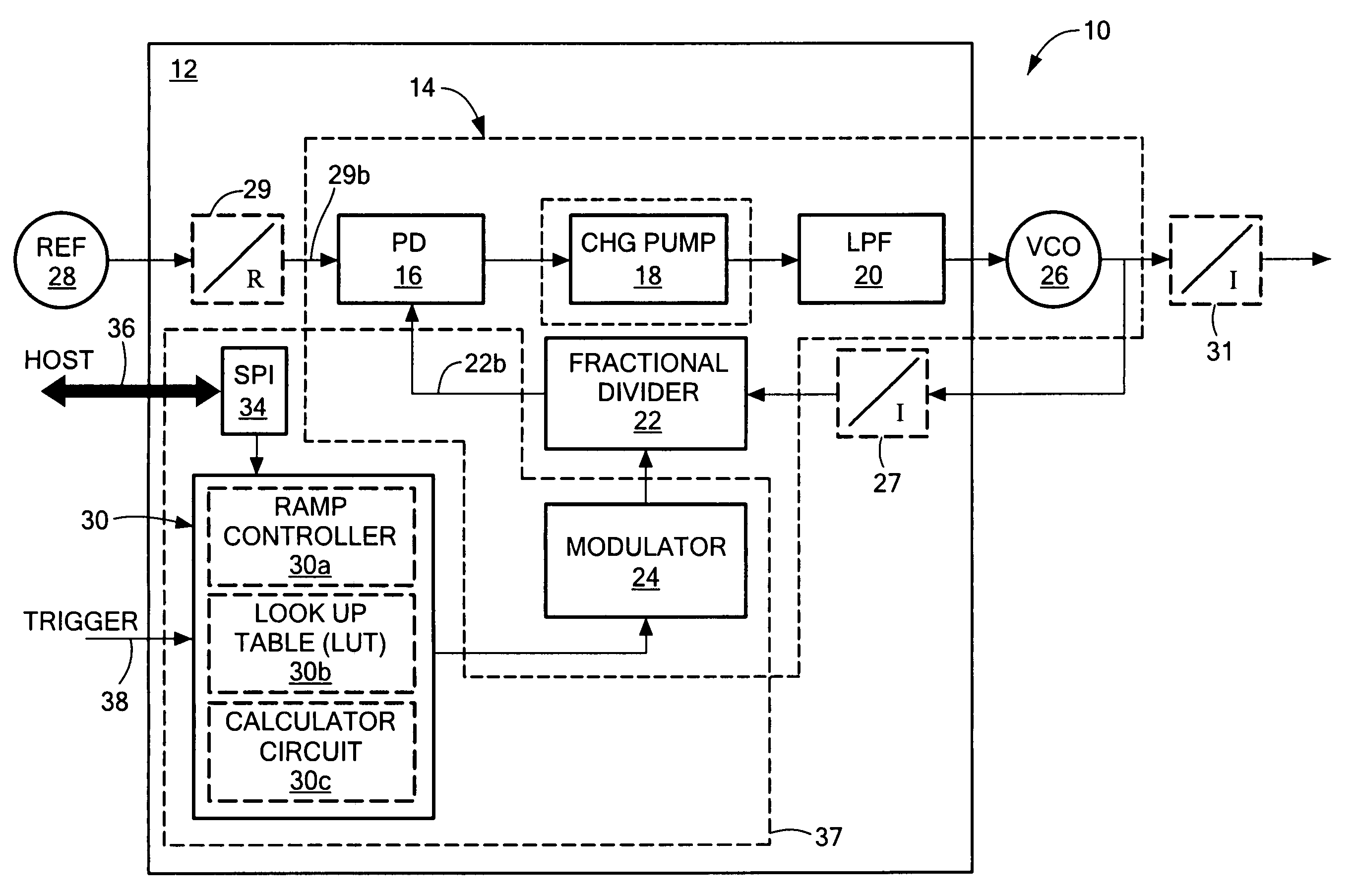
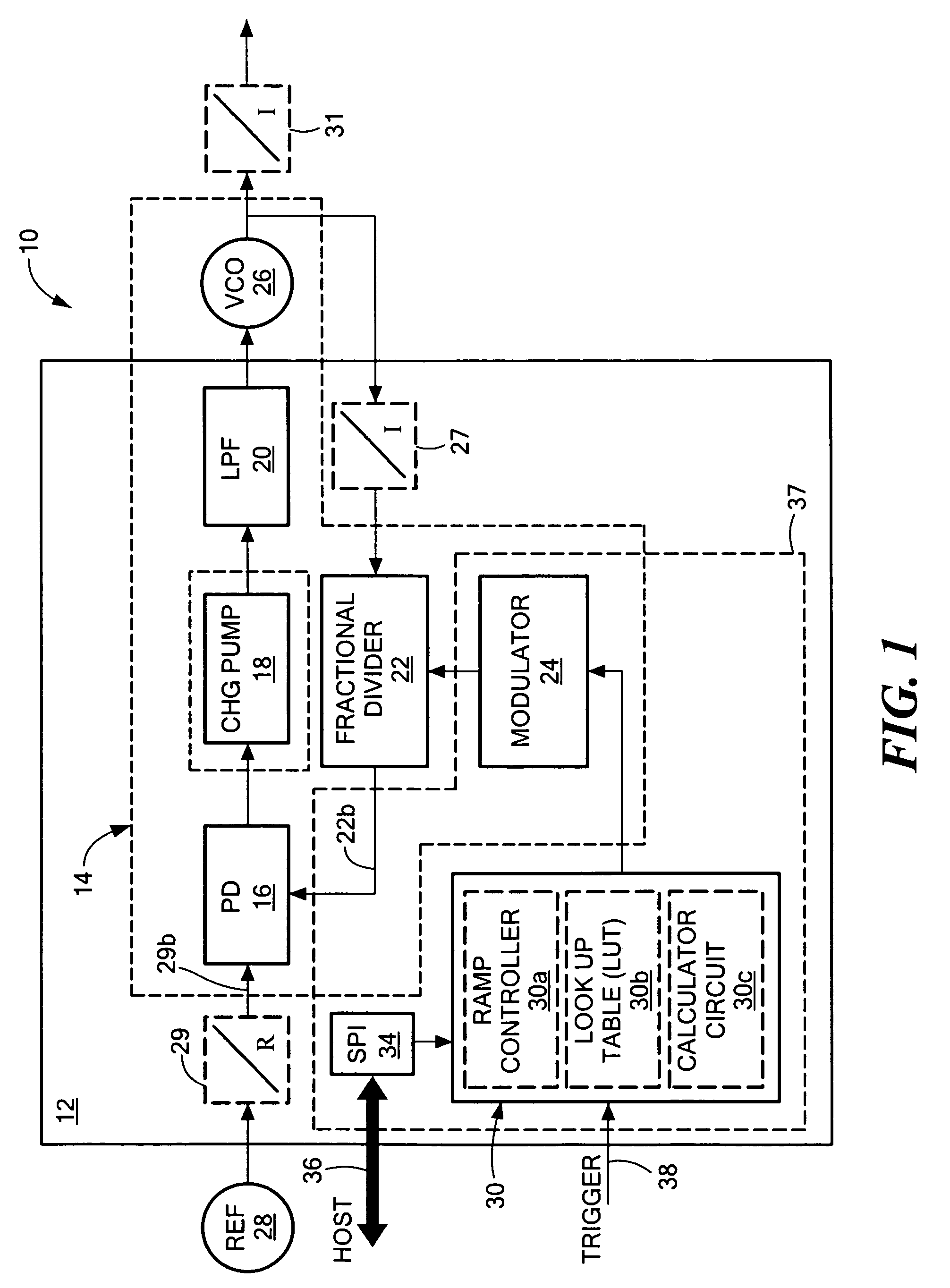
Integrated ramp, sweep fractional frequency synthesizer on an integrated circuit chip
a fractional frequency synthesizer and integrated circuit technology, applied in the direction of angle modulation, automatic control, electrical apparatus, etc., can solve the problems of high output frequency and large variation, add cost and complexity to the system, and increase so as to reduce the cost of external components, the effect of reducing the overhead of ramp frequency control
- Summary
- Abstract
- Description
- Claims
- Application Information
AI Technical Summary
Benefits of technology
Problems solved by technology
Method used
Image

Examples
Embodiment Construction
[0016]Aside from the preferred embodiment or embodiments disclosed below, this invention is capable of other embodiments and of being practiced or being carried out in various ways. Thus, it is to be understood that the invention is not limited in its application to the details of construction and the arrangements of components set forth in the following description or illustrated in the drawings. If only one embodiment is described herein, the claims hereof are not to be limited to that embodiment. Moreover, the claims hereof are not to be read restrictively unless there is clear and convincing evidence manifesting a certain exclusion, restriction, or disclaimer.
[0017]The invention is accomplished by adding an integrated controller and ramp circuit both of which are on-chip with the rest of the fractional frequency synthesizer to facilitate the generation of the frequency control ramp based solely on the programmed ramp data and either an external trigger or internally self generat...
PUM
 Abstract
Description
Claims
Application Information