Solid insulation for fluid-filled transformer and method of fabrication thereof

a technology of solid insulation and fluid-filled transformers, which is applied in the direction of power cables, magnetic bodies, cables, etc., can solve the problems of cellulose-based insulation systems limiting the operation efficiency of power transformers, affecting the normal operation and maximum operating temperatures of normal and maximum operating temperatures, and reducing the physical space needed for storage of transformers

Active Publication Date: 2011-12-27
PROLEC GE WAUKESHA INC
View PDF24 Cites 10 Cited by
  • Summary
  • Abstract
  • Description
  • Claims
  • Application Information

AI Technical Summary

Benefits of technology

[0005]At least in view of the above, it would be desirable to have.high-voltage, fluid-filled power transformers that are less susceptible to aging. It would also be desirable to have have.high-voltage, fluid-filled power transformers that have higher normal operating and maximum operating temperatures, as this would reduce the physical space needed to store the transformers.

Problems solved by technology

However, since cellulose naturally absorbs between 3 and 6 weight percent of moisture, a relatively costly process of heating under vacuum is typically performed before cellulose is suitable for use in a power transformer.
As more power is transferred, the higher losses due to higher current generate higher temperatures.
As such, cellulose-based insulation systems limit the operational efficiency of power transformers.

Method used


Image

  • Solid insulation for fluid-filled transformer and method of fabrication thereof
  • Solid insulation for fluid-filled transformer and method of fabrication thereof
  • Solid insulation for fluid-filled transformer and method of fabrication thereof

Examples


Embodiment Construction

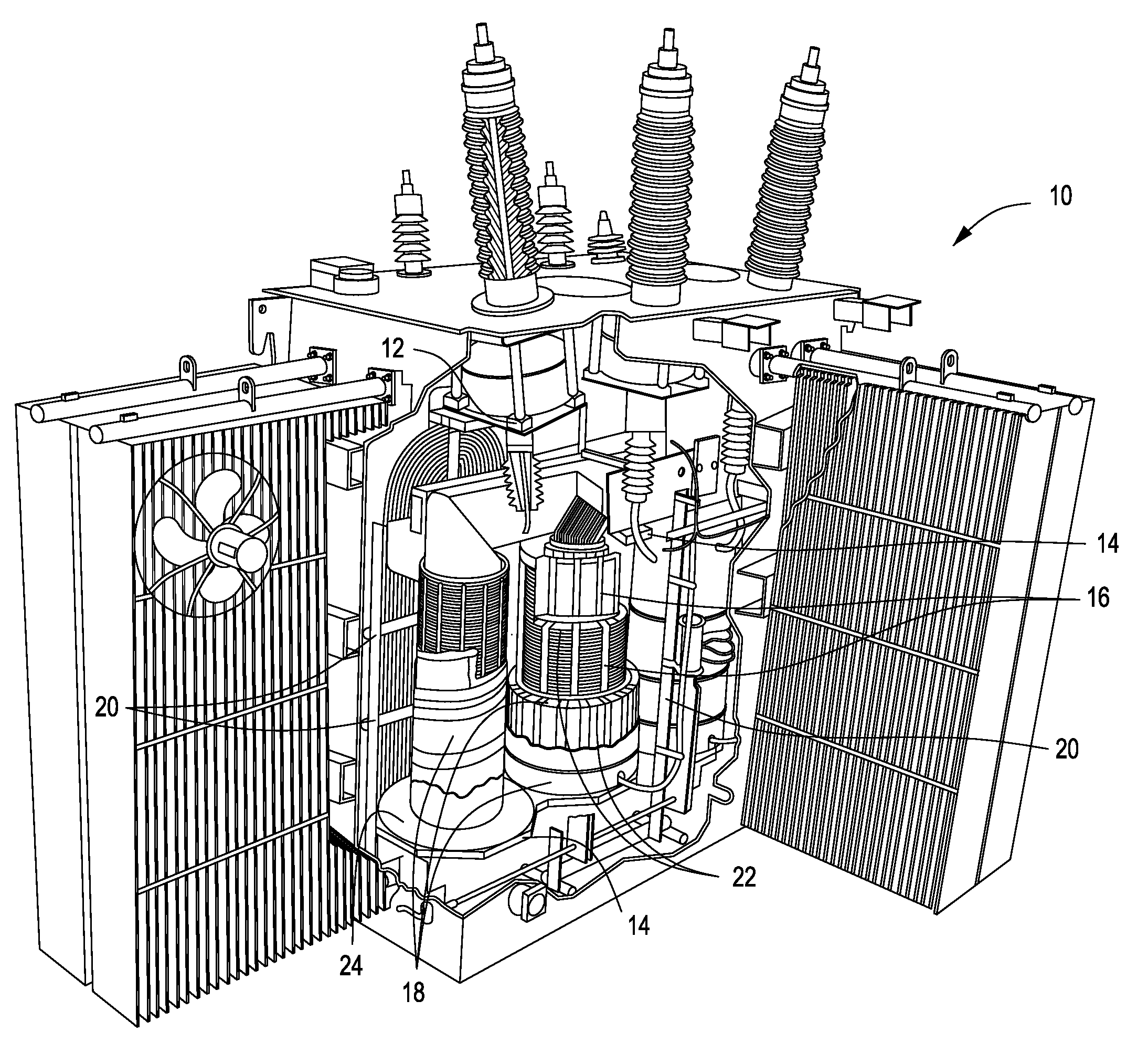
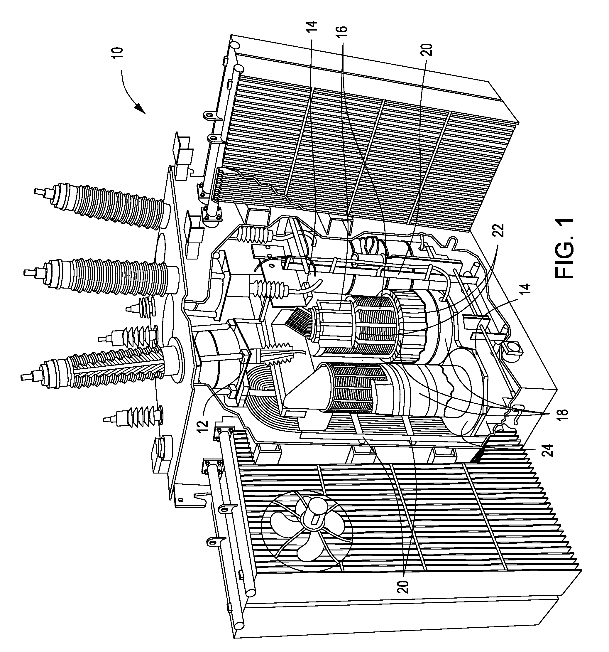
[0017]Embodiments of the present invention will now be described with reference to the drawing figures, in which like reference numerals refer to like parts throughout. FIG. 1 is a perspective view of a cross-section of a high-voltage, fluid-filled power transformer 10 according to an embodiment of the present invention. As illustrated in FIG. 1, the transformer 10 includes a variety of transformer components that all may have insulation positioned between and / or around them. More specifically, the transformer 10 includes current transformer (CT) supports 12, support blocks 14, locking strips 16, winding cylinders 18, lead supports 20, radical spacers 22 and end blocks 24. (For the purpose of clarity, the insulation is not illustrated in FIG. 1.)

[0018]In operation, a cooling fluid (e.g., an electrical or dielectric insulating fluid such as, for example, a napthenic mineral oil, a paraffinic-based mineral oil including isoparaffins, synthetic esters and natural esters (e.g., FR3™)) f...


PUM


Abstract

An insulation system for a fluid-filled power transformer that allows for operation of the transformer at higher temperatures and with lowered susceptibility to aging. The insulation system includes a plurality of fibers that are bound together by a solid binding agent. The solid binding agent may, for example, for sheaths around the fibers or may be in the form of dispersed particles that bind the fibers to each other. Also, a method of fabricating such an insulation system.

Description

FIELD OF THE INVENTION[0001]The present invention relates generally to insulation systems included in power transformers. The present invention also relates generally to methods of fabrication of power transformers including such insulation systemsBACKGROUND OF THE INVENTION[0002]Currently available high-voltage, fluid-filled power transformers utilize cellulose-based insulation materials that are impregnated with dielectric fluids. More specifically, such insulation systems include cellulose-based materials that are positioned between turns, between discs and sections, between layers, between windings and between components at high voltage and ground potential parts (e.g., cores, structural members and tanks).[0003]In order to operate, currently available transformers typically include insulation materials that have a moisture content of less than 0.5% by weight. However, since cellulose naturally absorbs between 3 and 6 weight percent of moisture, a relatively costly process of he...

Claims


Application Information

Patent Timeline
Patent Type & Authority Patents(United States)
IPC IPC(8): H01F27/08
CPCH01F27/12H01F27/32Y10T29/4902
Inventor GOLNER, THOMAS M.MEHTA, SHIRISH P.VARANASI, PADMA P.NEMEC, JEFFREY J.
Owner PROLEC GE WAUKESHA INC
Why Eureka
Try Eureka