Image input apparatus, image input method, personal authentication apparatus, and electronic apparatus

a technology of image input and input method, which is applied in the field of image input apparatus, image input method, personal authentication apparatus, electronic apparatus, can solve the problems of inadequate miniaturization of the apparatus, and achieve the effects of preventing division by zero or noise amplification, reducing the influence of lens positioning errors upon installation of the image pickup device 5, and improving m

Inactive Publication Date: 2011-12-27
RICOH KK
View PDF40 Cites 8 Cited by
  • Summary
  • Abstract
  • Description
  • Claims
  • Application Information

AI Technical Summary

Benefits of technology

[0077]On the other hand, as is shown in FIG. 10B, in a case where the convex face of a plano-convex lens faces the image surface side as with the lens 3a used in the present embodiment, although the overall MTF level may be decreased, variations in the MTF with respect to variations in the visual angle may be reduced and variations in the cutoff frequency may also be reduced. Thus, in the case of performing MTF correction operation, the convex face of a plano-convex lens is preferably arranged to face the image surface side and the convex face configuration is preferably adjusted so that the MTF may be uniform and limited within a predetermined range in order to maintain MTF performance throughout a relatively wide range of visual angles with a relatively small processing load. For example, the MTF characteristics represented by the thick solid line shown in FIG. 10B may be easily achieved with the present configuration. In addition to achieving improvements in MTF characteristics as is described above, it is noted that in-plane errors such as distortions and curvatures may be reduced by arranging the convex face of a plano-convex lens to face the image surface side. Also, the above-described advantageous effects may be equally obtained in the case of using a lens having a lens face with a negative power at the object side and a lens face with a positive power at the image surface side.
[0078]In the following, the MTF correction process performed by the correction operation unit 201 is described. It is noted that the correction operation unit 201 according to the present embodiment is configured to perform a process of extracting ommatidium images of a compound-eye image formed by the image pickup device 5 while excluding shade portions created by the light shielding member 4 before performing the correction process. Thus, in the present embodiment, the preprocessing unit 101 does not have to perform the process of extracting the ommatidium images other than the shade portions.
[0079]The image of an object that has been degraded by the lens 3a, that is, the intensity data of each individual ommatidium image of a compound-eye image may be expressed by the below formula (3):I(x,y)=FFT−1[FFT{S(x,y)}·OTF(x,y)]  (3)It is noted that in the above formula (3), x and y denote position coordinates of an ommatidium image, I denotes the intensity data of an ommatidium image, S denotes intensity data of the object, OTF denotes optical transfer function data of the lens 3a, FFT denotes a Fourier transfer operator, and FFT−1 denotes an inverse Fourier transfer operator. It is noted that the optical transfer function data OTF of the lens 3a may be obtained through autocorrelation of the pupil function of the lens 3a the using wave aberration data of the lens 3a obtained during the lens design stage.
[0080]The correction operation unit 201 uses the optical transfer function data OTF of the lens 3a that are calculated and stored in the memory 202 beforehand and performs computation of the below formula (4) on each ommatidium image of the compound image to correct image degradation caused by the lens 3a and generate an ommatidium image with improved MTF (and a compound-eye image corresponding to a collection of the corrected ommatidium images). It is noted that in the below formula (4), R denotes the intensity data of an ommatidium image after correction, α denotes a constant for preventing division by zero or noise amplification.
[0082]It is noted that when the optical transfer function does not change according to the change in the light ray angle, this means that the optical transfer function may not change even when the lens itself is slightly tilted, for example. Therefore, influences of lens positioning errors upon installing the image pickup device 5 may be reduced in such as case. Also, it is noted that when the light focusing performance level of the lens is high, the focal point may easily spread to cause image degradation even with a slight deviation of the image surface position with respect to the optical axis. However, in a case where the light focusing performance level of the lens is relatively low as in the example of FIG. 10B, the focal point may be prevented from spreading very far when the image surface position is slightly deviated from the optical axis. In this way, influences of errors in setting the distance between the lens and the image surface may be reduced, for example. Further, in a preferred embodiment, the lens array 3 may be coupled to the light shielding member 4 upon assembling the apparatus. Specifically, the convex faces of the lenses 3a facing the image surface side may engage corresponding openings (through holes) of the light shielding member 4 so that alignment of the lens array 3 and the light shielding member 4 may be facilitated, for example.
[0083]It is noted that a correction process that involves frequency filtering using FFT is described above as an illustrative example. However, a similar correction process may be performed through de-convolution using a point-spread function pattern, for example. It is noted that a process using a point-spread function pattern may be simpler than that using FFT (fast Fourier transform) so that the cost of the overall apparatus may be reduced in the case of fabricating a dedicated processing circuit, for example. In another preferred embodiment, optical transfer function data for correction operation may be calculated for each of plural visual angles and stored in the memory 202 beforehand so that correction may be performed using corresponding optical transfer function data for each of image regions corresponding to the different visual angles. In a further embodiment, correction may be performed on in-plane errors such as curvatures and distortions by estimating their error levels beforehand.

Problems solved by technology

The personal authentication apparatuses disclosed in Patent Documents 1, 2, and 3 use single-eye optical systems for inputting the vein pattern image so that restrictions are imposed with respect to the object distance and imaging distance and the apparatus may not be adequately miniaturized.

Method used


Image

  • Image input apparatus, image input method, personal authentication apparatus, and electronic apparatus
  • Image input apparatus, image input method, personal authentication apparatus, and electronic apparatus
  • Image input apparatus, image input method, personal authentication apparatus, and electronic apparatus

Examples


first embodiment

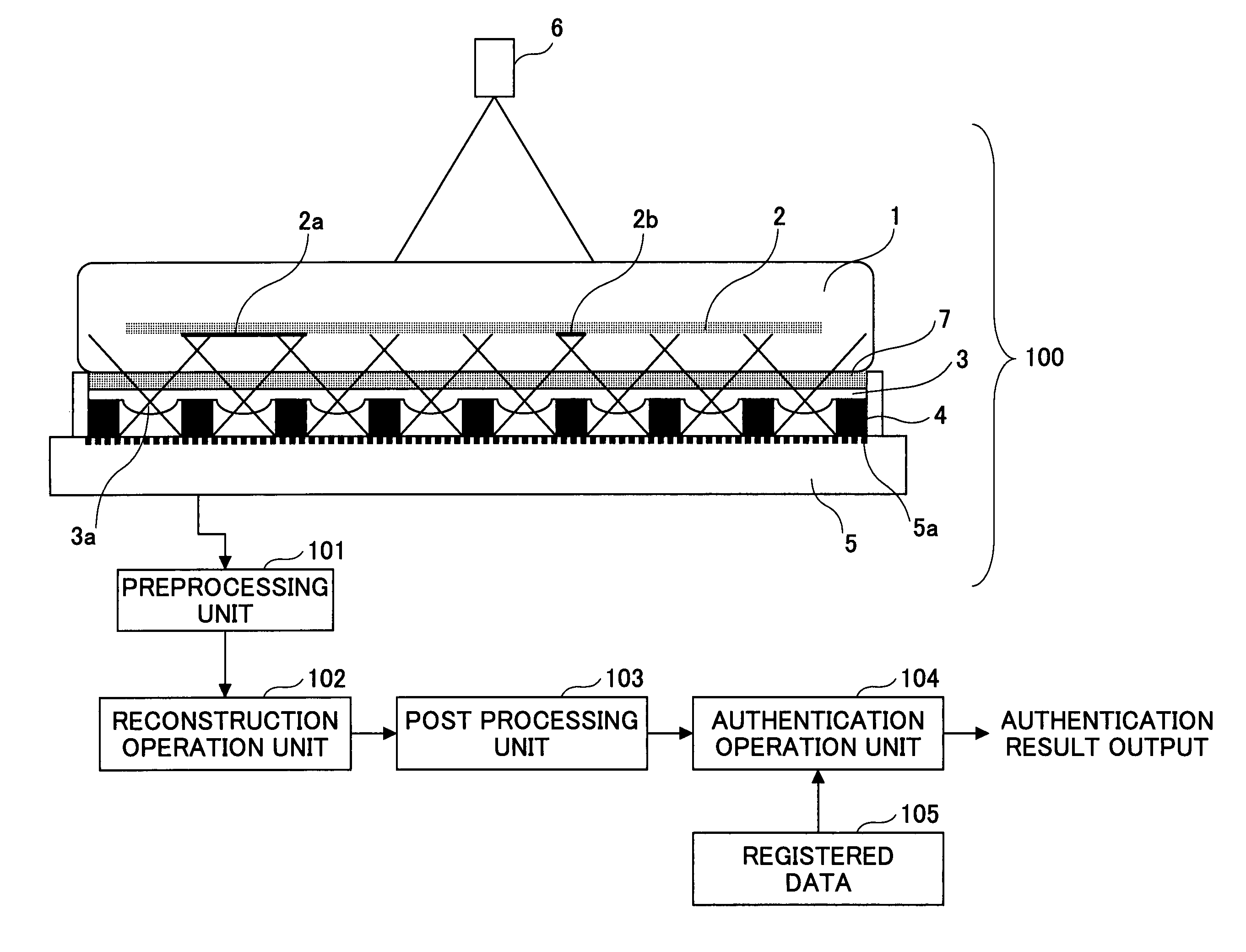
[0043]FIG. 1 is a diagram showing an image input apparatus and a personal authentication apparatus according to a first embodiment of the present invention. In FIG. 1, an imaging optical system 100, a preprocessing unit 101, a reconstruction operation unit 102, and a post processing unit 103 make up an image input apparatus. Also, an authentication operation unit 104 and a registered data memory 105 make up an authentication process part that performs a personal authentication process based on a vein pattern. Such an authentication process part and an image input apparatus make up a personal authentication apparatus according to the present embodiment.

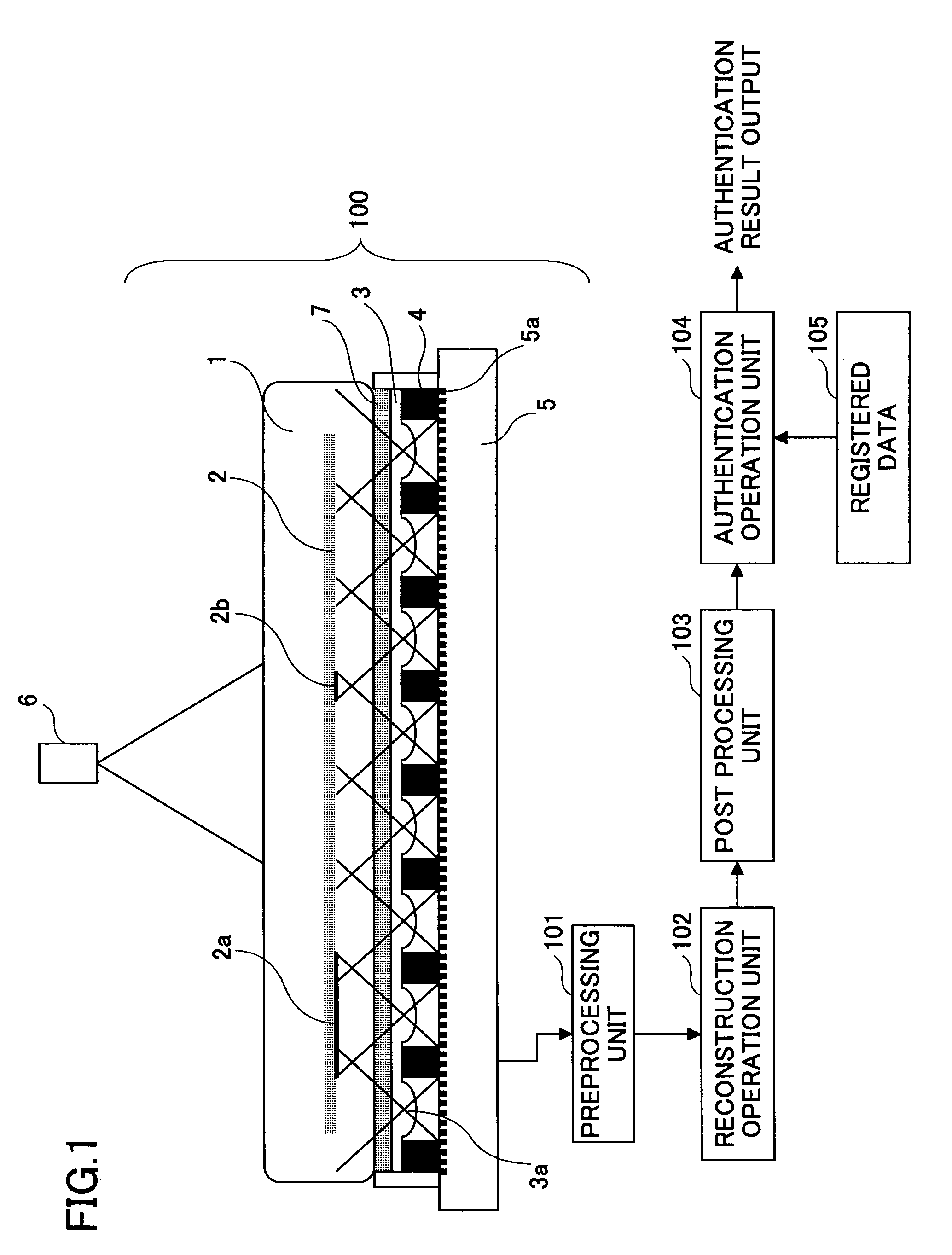
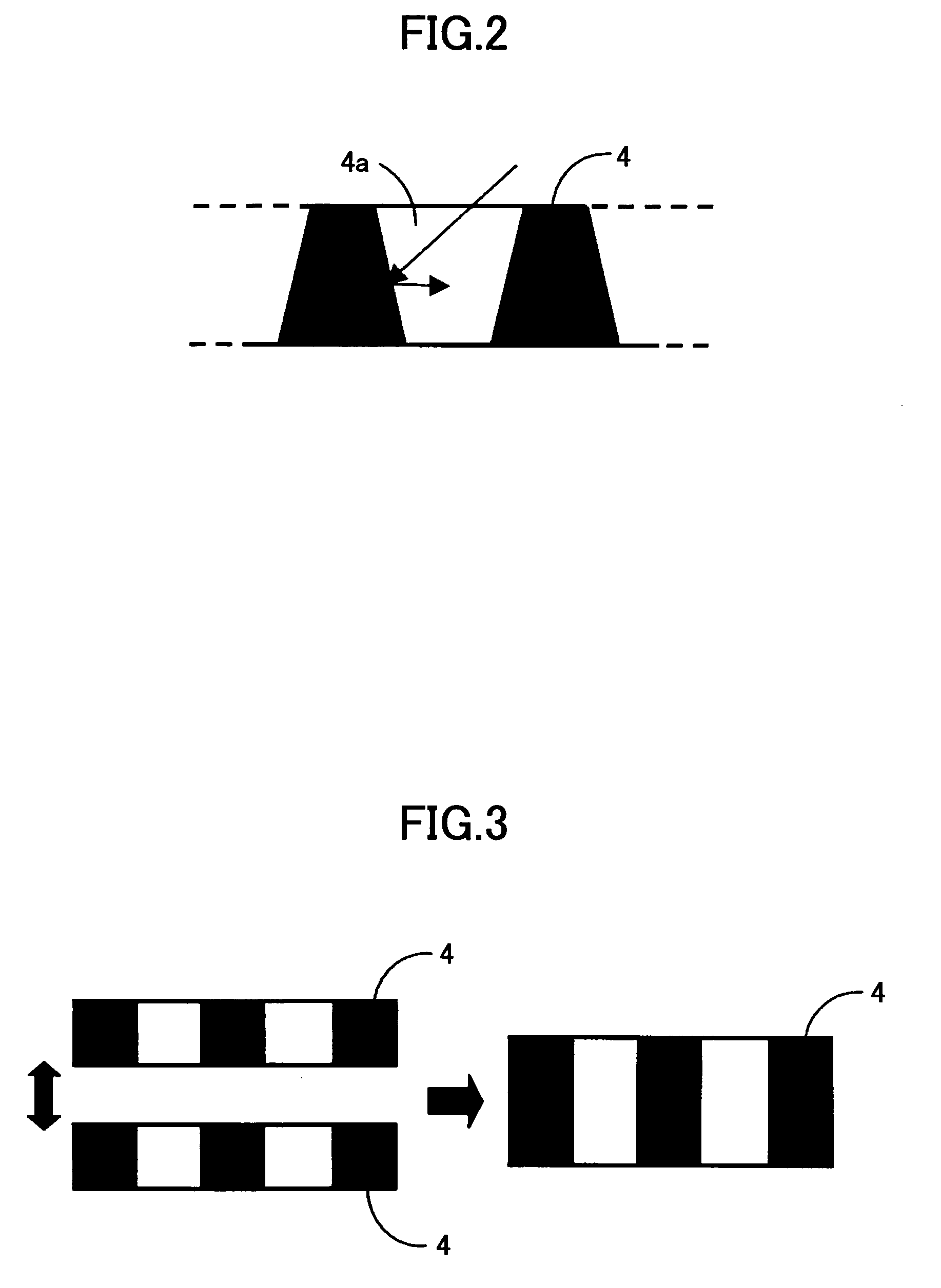
[0044]In FIG. 1, a finger (living body) 1 is placed on a certain location of the imaging optical system 100. The imaging optical system 100 captures an image of a vein 2 within the finger 1 as an object, and inputs the captured image. The imaging optical system 100 includes a light source 6, a lens array 3, a light shielding member 4, ...

second embodiment

[0073]FIG. 9 is a diagram illustrating an image input apparatus and a personal authentication apparatus according to a second embodiment of the present invention. The apparatus according to the present embodiment differs from that of the first embodiment in that it includes a correction operation unit 201 and a memory 202 as a correction processing part for correcting (e.g., through MTF correction) image degradation caused by the lenses 3a of the lens array 3. It is noted that other features of the apparatus according to the present embodiment may be substantially identical to the first embodiment. It is noted that optical transfer function (OTF) data pertaining to the plano-convex lens 3a having its convex face facing the image surface are stored in the memory 202 beforehand.

[0074]FIGS. 10A and 10B are graphs illustrating the relationship between the MTF corresponding to the gain of the optical transfer function of a plano-convex lens and the visual angle of an object in a case whe...

third embodiment

[0085]It is noted that the optical transfer function of a lens may vary depending on the object distance (i.e., distance from the object 2 to the lens array 3). Particularly, in an imaging optical system of an image input apparatus according to an embodiment of the present invention where the object is positioned relatively close to the lens array 3, the optical transfer function may greatly vary in response to variations in the object distance.

[0086]FIG. 11 is a graph illustrating exemplary variations in MTF characteristics according to the object distance in a plano-convex lens having its convex face facing the image surface side as in the case of FIG. 10B. Specifically, in FIG. 11, MTF characteristics at a predetermined visual angle when the object distance is equal to A, B, and C are illustrated by a thin solid line, a dotted line, and a dashed line, respectively. As can be appreciated from this example, in a case where variations in the object distance cannot be disregarded (i....


PUM


Abstract

An image input apparatus that inputs an image of an object residing within a living body is disclosed. The image input apparatus includes a light source that irradiates near infrared light on the living body, a lens array arranged at a position facing the living body and including plural lenses each having a face with zero or negative power arranged at a side facing the living body and a face with positive power arranged at a side facing an image surface, an imaging unit arranged at the image surface side of the lens array that forms a compound-eye image corresponding to a collection of ommatidium images formed by the lenses of the lens array, and a reconstruction unit that reconstructs a single image from the compound-eye image using a parallax between the ommatidium images. The reconstructed single image is input as the image of the object.

Description

TECHNICAL FIELD[0001]The present invention relates to an input apparatus and an input method suitable for inputting an image of an object within a living body (e.g., veins of a finger, subdermal fingerprints), and a personal authentication apparatus that uses such the image of such an object.BACKGROUND ART[0002]Patent Document 1 (Japanese Laid-Open Patent No. 2004-27281), Patent Document 2 (Japanese Laid-Open Patent No. 2005-92375), and Patent Document 3 (Japanese Laid-Open Patent No. 7-21373) disclose embodiments of a personal authentication apparatus that irradiates infrared light or near infrared light on a finger to capture an image of a vein pattern within the finger and perform personal authentication based on the vein pattern.[0003]Also, Patent Document 4 (Japanese Patent No. 3705766), Patent Document 5 (Japanese Laid-Open Patent No. 2001-61109), and Non-Patent Document 1 (Rui Shogenji et al., “Development of Thin Image Input Apparatus using Compound-Eye Optical System”, The ...

Claims


Application Information

Patent Timeline
Patent Type & Authority Patents(United States)
IPC IPC(8): H04N5/228A61B5/117G02B3/00G06T1/00H04N5/225H04N5/335H04N5/369
CPCA61B5/0059A61B5/1172G06K9/0004G06T1/0007H04N5/2254H04N5/2628G06K2009/00932G06V40/1318G06V40/14A61B5/117G06V10/10G06F18/00
Inventor MORITA, NOBUHIROYAMANAKA, YUJIISEKI, TOSHIYUKINASUKAWA, TOSHIMICHIKOSUGA, SHINICHITAKAHASHI, HIROAKITAKAHASHI, AKIRA
Owner RICOH KK
Why Eureka
Try Eureka