
Wireless communication method and apparatus for dynamically adapting packet transmission rates

a dynamic transmission and packet technology, applied in the field of data transmission, can solve the problems of not always being able to achieve acceptable quality at higher data rates, system b>10/b> does not provide a mechanism to transfer perceived channel quality in terms of received signal power, snr or packet, etc., and achieve the effect of quick establishment of the best data transmission rate available and acceptable quality of servi

Inactive Publication Date: 2011-12-27
INTERDIGITAL TECH CORP
View PDF16 Cites 5 Cited by
  • Summary
  • Abstract
  • Description
  • Claims
  • Application Information

AI Technical Summary

Benefits of technology

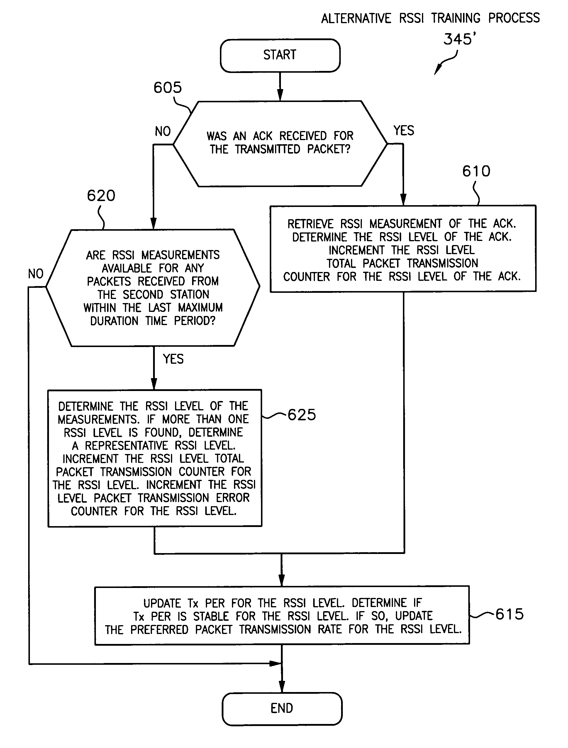
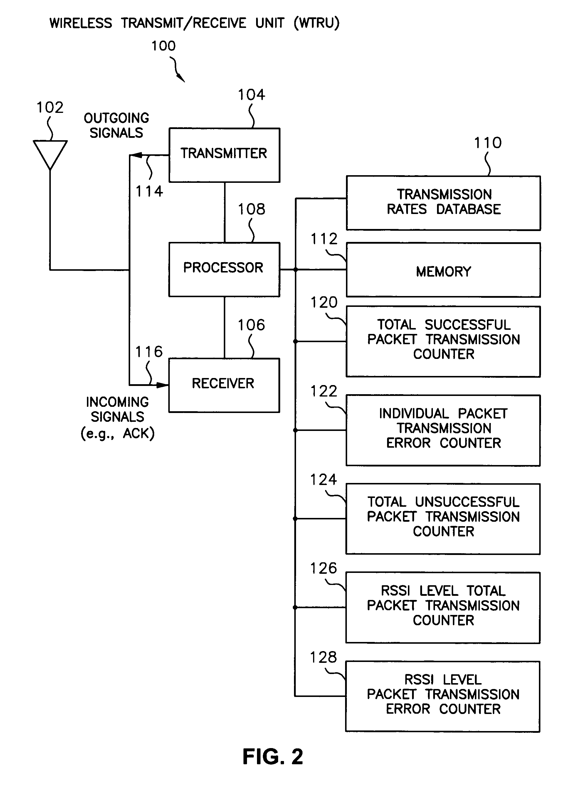
The present invention is related to a method and apparatus for adjusting the transmission rate of packets transmitted to a second transceiver based on signals the first transceiver receives from the second transceiver. The invention allows for the selection of a preferred data transmission rate based on measurements made at the transceiver, such as received signal strength (Rx power) of packets received at the transceiver and the Tx PER of signals transmitted by the transceiver. The transceiver can quickly establish the best data transmission rate available while maintaining an acceptable quality of service (QoS) and can thereafter adapt its transmission rate in response to changing fading conditions.

Problems solved by technology

However, it is not always possible to achieve acceptable quality at higher data rates, since they require relatively higher signal-to-noise ratios (SNRs) at the receiver.
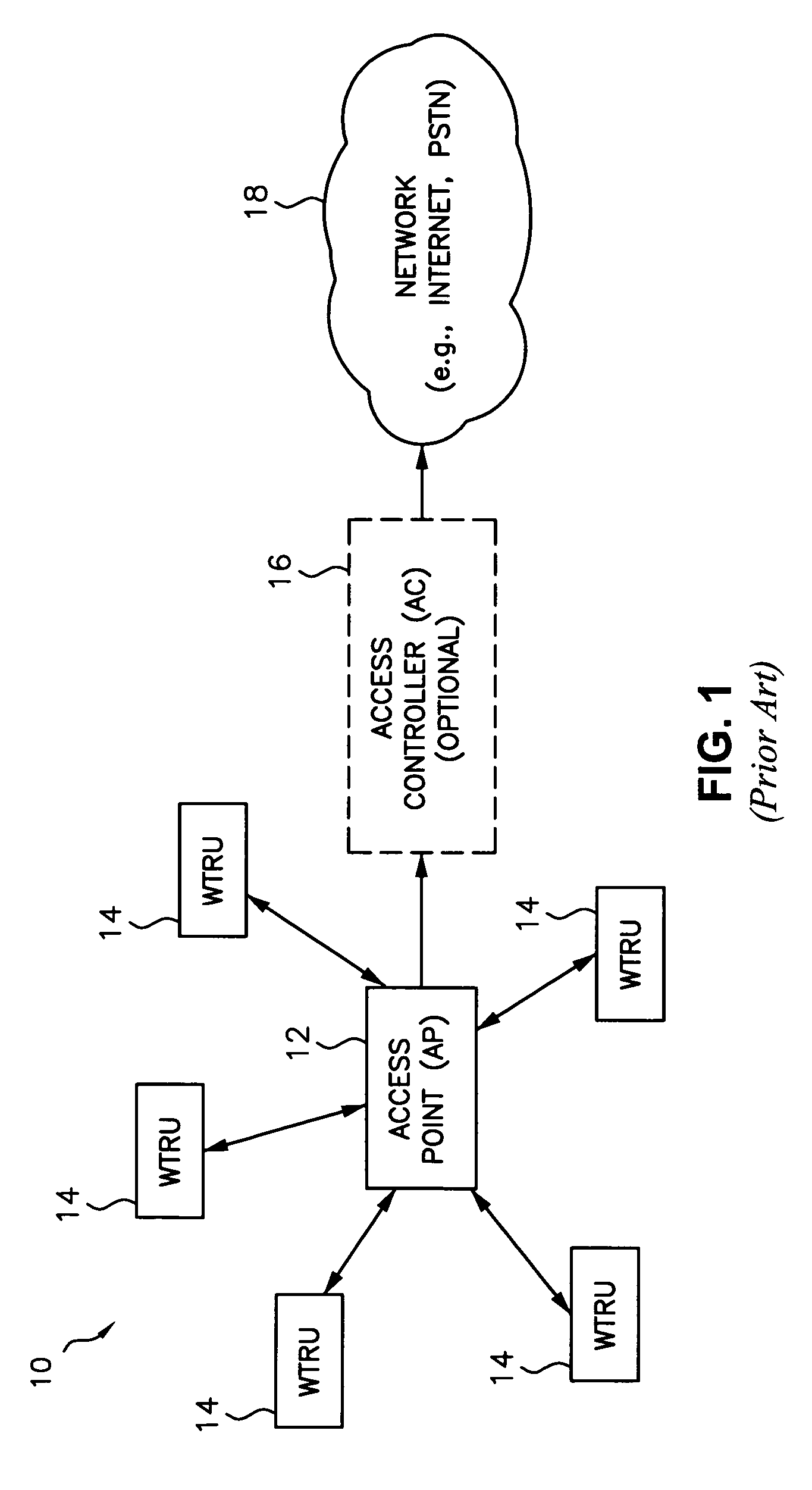
However, system 10 does not provide a mechanism to transfer perceived channel quality in terms of received signal power, SNR or packet error rate (PER) to the source of the packets.

Method used


Image

  • Wireless communication method and apparatus for dynamically adapting packet transmission rates
  • Wireless communication method and apparatus for dynamically adapting packet transmission rates
  • Wireless communication method and apparatus for dynamically adapting packet transmission rates

Examples


Embodiment Construction

The term AP as used hereinafter includes, but is not limited to, a base station, a Node B, a site controller, a wireless router or any other interfacing device in a wireless environment that provides WTRUs with wireless access to a network with which the AP is associated.

The term WTRU as used hereinafter includes, but is not limited to, a client station (CS), user equipment (UE), station (STA), mobile station, fixed or mobile subscriber unit, pager, or any other type of user device capable of operating in a wireless environment. Such WTRUs include personal communication devices, such as phones, video phones, and Internet ready phones that have network connections. In addition, WTRUs include portable personal computing devices, such as PDAs and notebook computers with wireless modems that have similar network capabilities. WTRUs that are portable or can otherwise change location are referred to as mobile units.

A wireless connection as used hereinafter is defined as a wireless communi...


PUM


Abstract

A method and apparatus for use by a first transceiver, (e.g., wireless transmit / receive unit (WTRU), access point (AP), node) for adjusting the transmission rate of packets transmitted to a second transceiver based on signals the first transceiver receives from the second transceiver. In one embodiment, a transmission packet error rate (Tx PER) process is used to adjust the packet transmission rate. In another embodiment, a relative signal strength indicator (RSSI)-based process is used to determine the RSSI of packets received at the first transceiver from the second transceiver for adjusting the packet transmission rate. In another embodiment, transmission quality indicators are measured at the second transceiver and are sent to the first transceiver, which derives a new packet transmission rate therefrom. The Tx PER and RSSI-based processes may be used individually, in combination, or in conjunction with other processes.

Description

FIELD OF INVENTIONThe present invention is related to data transmission in a wireless communication system. More particularly, the present invention is related to dynamically adapting packet transmission rates in response to varying fading conditions.BACKGROUNDWireless communication systems, such as wireless local area networks (WLANs), are well known in the art. Generally, such systems comprise transceivers, (i.e., communication stations, (STAs)), which transmit and receive wireless communication signals between each other. Depending upon the type of system, transceivers may take the form of an access point (AP), a wireless transmit / receive unit (WTRU), a node or the like.FIG. 1 shows a conventional wireless communication system 10 in which an AP 12 provides communication services to a plurality of WTRUs 14. The AP 12 can communicate with a network 18 through an optional access controller (AC) 16, thereby providing additional network services to the WTRUs 14, such as access to the ...

Claims


Application Information

Patent Timeline
Patent Type & Authority Patents(United States)
IPC IPC(8): H04W4/00H04W28/18
CPCH04L1/0015H04L1/203H04L1/1867H04L1/0002H04W28/18
Inventor ROY, VINCENTCAVE, CHRISTOPHER
Owner INTERDIGITAL TECH CORP
Learn More