
Temperature sensor with leads

a technology of temperature sensor and lead, which is applied in the direction of resistor details, instruments, heat measurement, etc., can solve the problems of reducing reliability, increasing resistance value, and avoiding measurement errors between measured temperatures, so as to avoid damage, avoid damage, and ensure the effect of safety

Active Publication Date: 2012-01-10
MURATA MFG CO LTD
View PDF5 Cites 16 Cited by
  • Summary
  • Abstract
  • Description
  • Claims
  • Application Information

AI Technical Summary

Benefits of technology

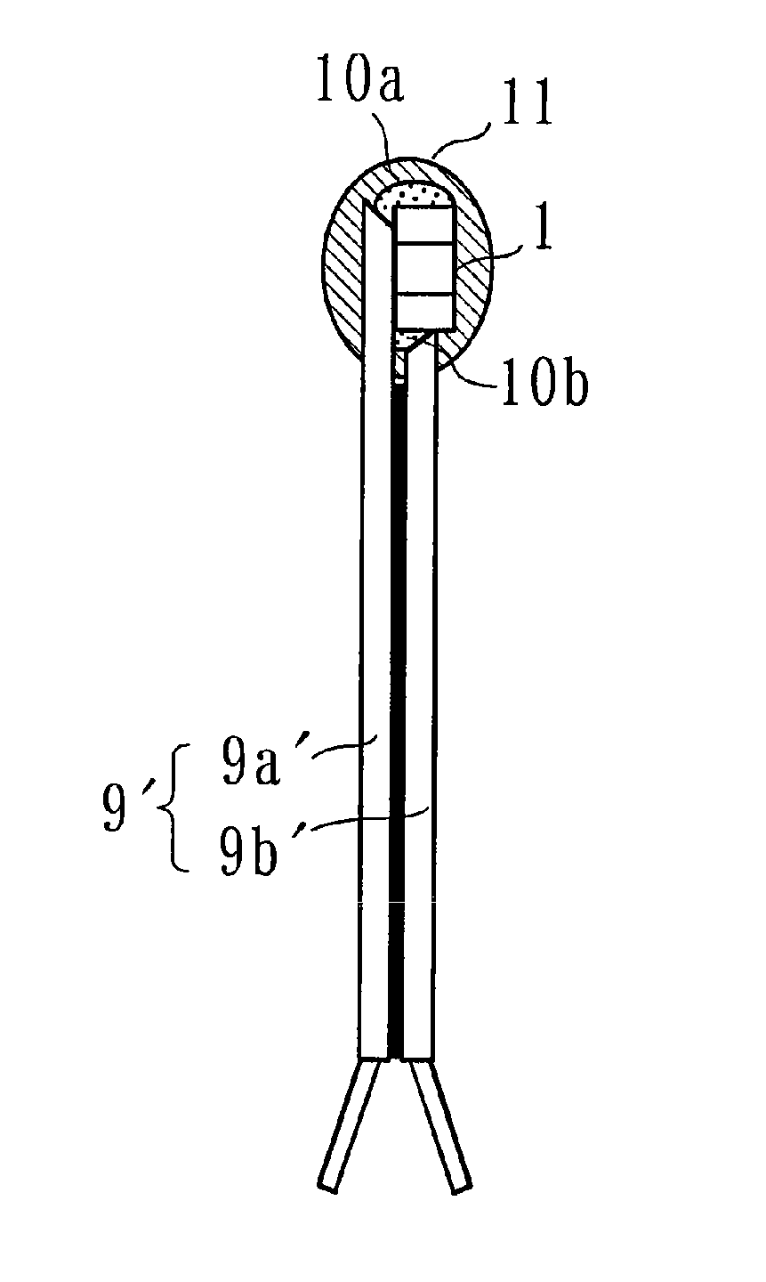
The present invention provides a temperature sensor with leads that have stable electrical connection with the temperature sensor, even under extreme thermal or mechanical stress. The leads have a metal line with an insulating member covering the metal line. The metal line is exposed at the tip of the lead and the end surface of the terminal electrode, allowing for a stable attachment of the temperature sensor to the leads. The leads have a predetermined angle with the terminal electrodes, which further strengthens the attachment. The temperature sensor can be fixed stably at a predetermined position and has high sensitivity and reliability at low cost.

Problems solved by technology

As a result, a part of the electrode layers 102a and 102b may become separated from the thermistor body 101, this may increase the value of resistance, and thus a problem arises in which a measurement error is present between a measured temperature and an actual one.
The stress indicated by the arrows a and b caused by an excessive thermal stress may break the thermistor body 101 itself, and the breakage may result in reduced reliability.
This reduces the distance between the electrodes and increases the risk of a short circuit.
Accordingly, there is also a problem in which it is difficult to further reduce the size.

Method used


Image

  • Temperature sensor with leads
  • Temperature sensor with leads
  • Temperature sensor with leads

Examples


applied examples

[0150]A thermistor with leads can be applied in various fields that need temperature detection.

[0151]For example, a temperature sensing portion of the thermistor can be arranged at a maximum heat point of a battery cell of a cellular phone as a measurement point. Accordingly, charging and discharging the battery can be controlled with high precision.

[0152]FIGS. 19 and 20 illustrate examples in which a thermistor with leads is applied for temperature detection in a fuel cell.

[0153]In the fuel cell, three battery cells 36a, 36b, and 36c are preferably arranged in parallel inside a battery casing 35, and a control board 37 is arranged at the end of the battery casing 35, for example.

[0154]In measuring the temperature of the battery cell 36b, because the leads are mounted on the control board 37, the measurement point and the control board 37 are unavoidably remote.

[0155]In such a case, as illustrated in FIG. 19, the use and mounting of the thermistor 9′ with leads enables the temperatu...


PUM

PropertyMeasurementUnit
widthaaaaaaaaaa
lengthaaaaaaaaaa
lengthaaaaaaaaaa

Abstract

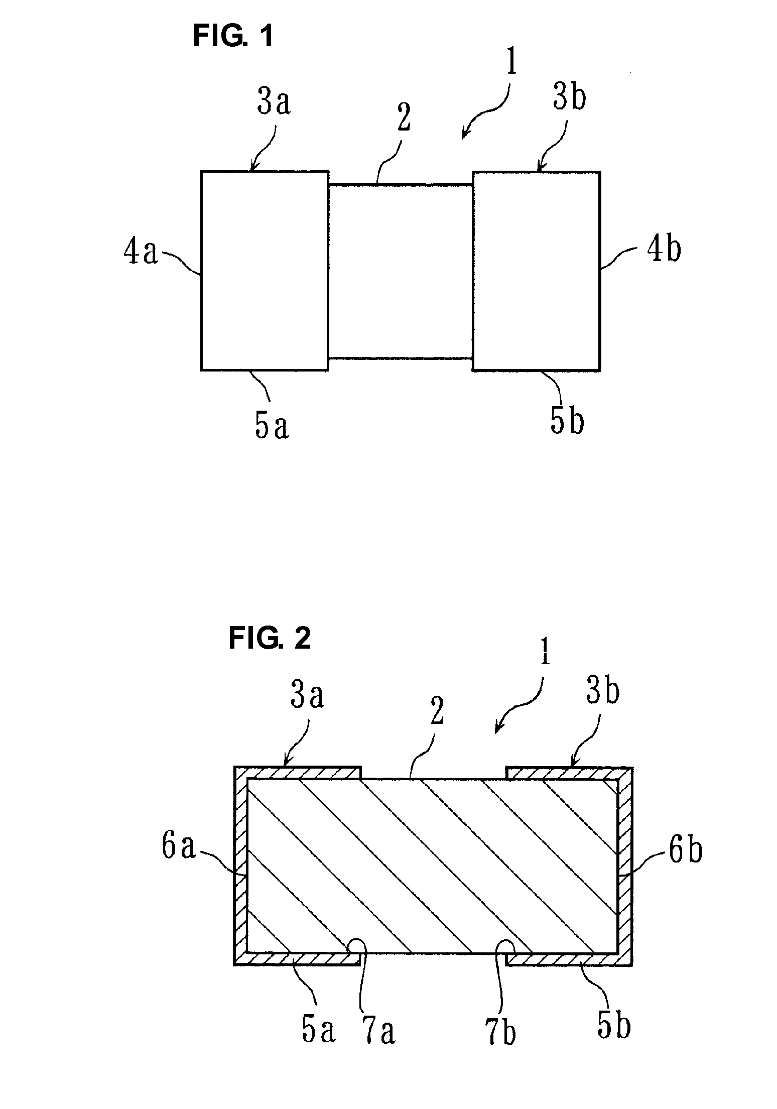
A thermistor includes a thermistor body and terminal electrodes disposed at both ends of the thermistor body. A first lead is longer than a second lead. The first and second leads include tips having inclined shapes that are cut such that metal lines are surface-exposed, respectively. The thermistor body is attached at a predetermined side position of the first lead such that the first lead and a side folding portion of the terminal electrode form a predetermined angle θ. The terminal electrode and the first lead are connected to each other through solder, and the second lead and the terminal electrode are connected to each other through solder. This can prevent the occurrence of damage even if an excessive thermal stress is applied. The temperature sensor with leads having stable electric connection with the temperature sensor that has satisfactory detection sensitivity and high reliability is achieved.

Description

BACKGROUND OF THE INVENTION[0001]1. Field of the Invention[0002]The present invention relates to a temperature sensor with leads, and more specifically, to a temperature sensor with leads suited for measuring a temperature at a location remote from a control board on which a temperature sensor is mounted.[0003]2. Description of the Related Art[0004]A personal computer or a power assisted bicycle may use a relatively large secondary battery or a plurality of fuel cells arranged in parallel in some cases. In such cases, because a location where a temperature of a secondary battery or fuel cells is to be measured is remote from a control board on which a temperature sensor is mounted, a temperature sensor with leads utilizing a long lead is employed. The use of such a temperature sensor with leads enables the leads to be fixed on the control board (e.g., a printed circuit) by soldering and also allows a temperature sensing portion of the temperature sensor to be arranged adjacent to a ...

Claims


Application Information

Patent Timeline
Patent Type & Authority Patents(United States)
IPC IPC(8): G01K7/00
CPCG01K7/223H01C1/144H01C7/008G01K7/22H01C7/04
Inventor KAWASE, MASAHIKOTSUJI, SHIRO
Owner MURATA MFG CO LTD
Learn More